Service Manual SIPLACE SmartFeeder.pdf - 第99页
7 Repairs to SmartFeeder 8 mm X / Xi 7.2 Rear Sliding Guide Service Manual SIPLACE SmartFeeder 4 - 8 mm X / Xi SIPLACE SmartFeeder 2 x 8 mm X / Xi 11/2020 99 7.2 Rear Sliding Guide Required spare part Fig.29: Sliding gu…
7 Repairs to SmartFeeder 8 mm X / Xi
7.1 Front sliding guide/sliding foil
98 Service Manual SIPLACE SmartFeeder 4 - 8 mm X / Xi SIPLACE SmartFeeder 2 x 8 mm X / Xi 11/2020
7.1 Front sliding guide/sliding foil
Required spare part
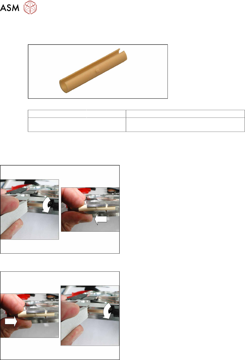
Fig.28: Sliding foil
Feeder module Item no. Designation
SmartFeeder 8mmX
SmartFeeder 8mmXi
03019604Sxx Sliding foil, X-feeder JUM-S-06LY
Tools required
●
Sliding foil remover
7.1.1 Removing the Sliding Foil
► Place the feeder module carefully down on its
side, onto a stable, level and clean surface.
► Place the sliding foil remover into the sliding
guide, as shown in the diagram.
► Lever the sliding foil out of the engaged position.
► Pull the sliding foil out of the sliding guide, to-
wards the front.
7.1.2 Fitting the Sliding Foil
► Press the sliding foil slightly together.
► Push the sliding foil into the sliding guide, from
the front, as far as the end stop.
► Turn the sliding foil, until the slit can be fully seen
and the sliding foil engages audibly.
7 Repairs to SmartFeeder 8 mm X / Xi
7.2 Rear Sliding Guide
Service Manual SIPLACE SmartFeeder 4 - 8 mm X / Xi SIPLACE SmartFeeder 2 x 8 mm X / Xi 11/2020 99
7.2 Rear Sliding Guide
Required spare part
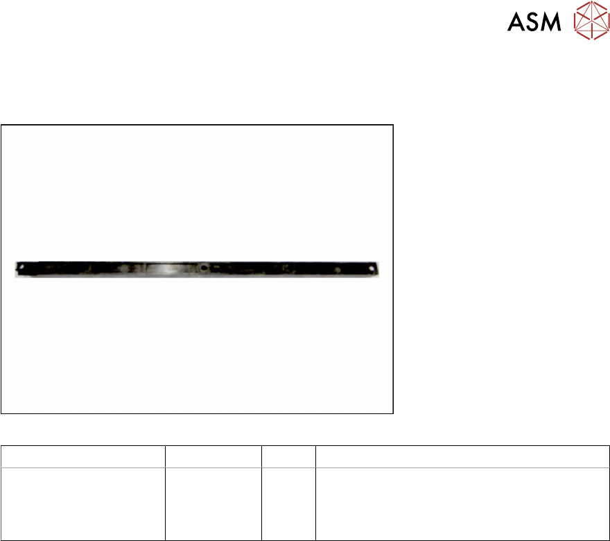
Fig.29: Sliding guide, back
Feeder module Item no. Type Designation
SmartFeeder 8mmX
SmartFeeder 8mmXi
03003994-xx
03010209-xx
03158711-xx
A
B
Sliding guide / back L200
ISO 7045 - M2.5 x 6-A2-50-H (1x)
Fillister head self-tapping screw DIN7981
2.9x9.5 (3x)
Tools required
●
TORX screwdriver 0.6Nm, size T8
7 Repairs to SmartFeeder 8 mm X / Xi
7.2 Rear Sliding Guide
100 Service Manual SIPLACE SmartFeeder 4 - 8 mm X / Xi SIPLACE SmartFeeder 2 x 8 mm X / Xi 11/2020
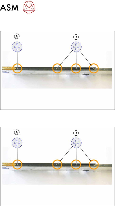
7.2.1 Removing the Sliding Guide
► Turn the feeder module so that its underside is at
the top.
► Remove the Phillips screw from the left side.
► Remove the three fillister head self-tapping
screws on the righthand side.
► Lift the gliding slide upwards and off.
7.2.2 Fitting the Sliding Guide
► Turn the feeder module so that its underside is at
the top.
► Fit the guiding slide to the underside of the feeder
module.
Observe the arrangement of the drilled holes in
the guiding slide.
► Push the guiding slide to the left (front) towards
the front guiding slide, as far as the stop.
► Now lower the two snap tabs of the guiding slide
into the openings provided on the underside of
the feeder module.
► Fasten the sliding guide on the left side to the
feeder module, using the Phillips screw (ISO
7045 - M2.5 x 6-A2-50-H) tightened to 0.6N.
► Fasten the sliding bearing on the righthand side
with the three fillister head self-tapping screws
(DIN7981 2.9x9.5), using 0.6Nm, to the feeder
module.