SIPLACE D2I 规格说明书英文版 - 第13页
13 Placement Heads Nozzle Changers Magazine for 12 type 9xx nozzles Nozzle cha nger for the 6-nozzle Collect & Place head (NCH6) Magazine for 6 type 9xx nozzles Magazine for 6 type 8xx nozzles Description Nozzle chan…
12
Placement Heads
Technical Data
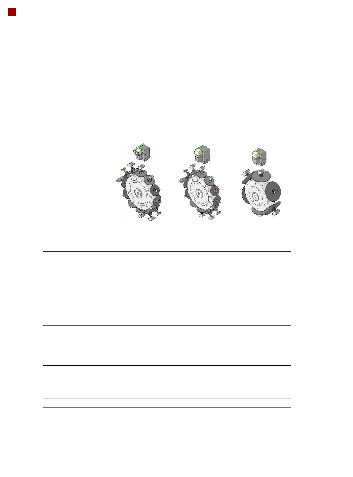
12-nozzle
Collect&Place head
CO camera type 28
12-nozzle
Collect&Place head
CO camera type 30
6-nozzle
Collect&Place head
CO camera type 30
Component range
a
a) Please note that the range of components that can be placed is also affected by the pad geometry, cus-
tomer-specific standards, component packaging tolerances and component tolerances
0402 to PLCC44, BGA,
µBGA, flip-chip, TSOP,
QFP, SO to SO32,
DRAM
01005
b
to flip-chip, bare
die, PLCC44, BGA,
µBGA, TSOP, QFP, SO
to SO32, DRAM
b) With 01005 package
0201to 27 x 27 mm²
Component specification
max. height
min. lead pitch
min. lead width
min. ball pitch
min. ball diameter
min. dimensions
max. dimensions
max. weight
6 mm
0.5 mm
0.2 mm
0.35 mm
0.2 mm
1.0 x 0.5 mm²
18.7 x 18.7 mm²
2 g
6 mm
0.3 mm
0.15 mm
0.25 mm
0.14 mm
0.4 x 0.2 mm²
18.7 x 18.7 mm²
2 g
8.5 mm
0.3 mm
0.15 mm
0.25 mm
c
0.35 mm
d
0.14 mm
c
0.2 mm
d
0.6 x 0.3 mm²
27 x 27 mm²
5 g
c) For components < 18 x 18 mm²
d) For components 18 x 18 mm²
Programmable placement
force
2.4 N - 5.0 N 2.4 N - 5.0 N 2.4 N - 5.0 N
Nozzle types 9xx 9xx 8xx, 9xx
X/Y accuracy
e
e) The accuracy value was measured using the vendor-neutral IPC standard
± 50 µm/3
± 67 µm/4
± 50 µm/3
± 67 µm/4
± 52.5 µm/3
± 70 µm/4
Angular accuracy ± 0.53°/3
± 0.71°/4
± 0.53°/3
± 0.71°/4
± 0.225°/3
± 0.3°/4
Component range 98% 98.5% 99.5%
Component camera type 28 30 30
Illumination levels 5 5 5
Possible illumination level
settings
256
5
256
5
256
5
13
Placement Heads
Nozzle Changers
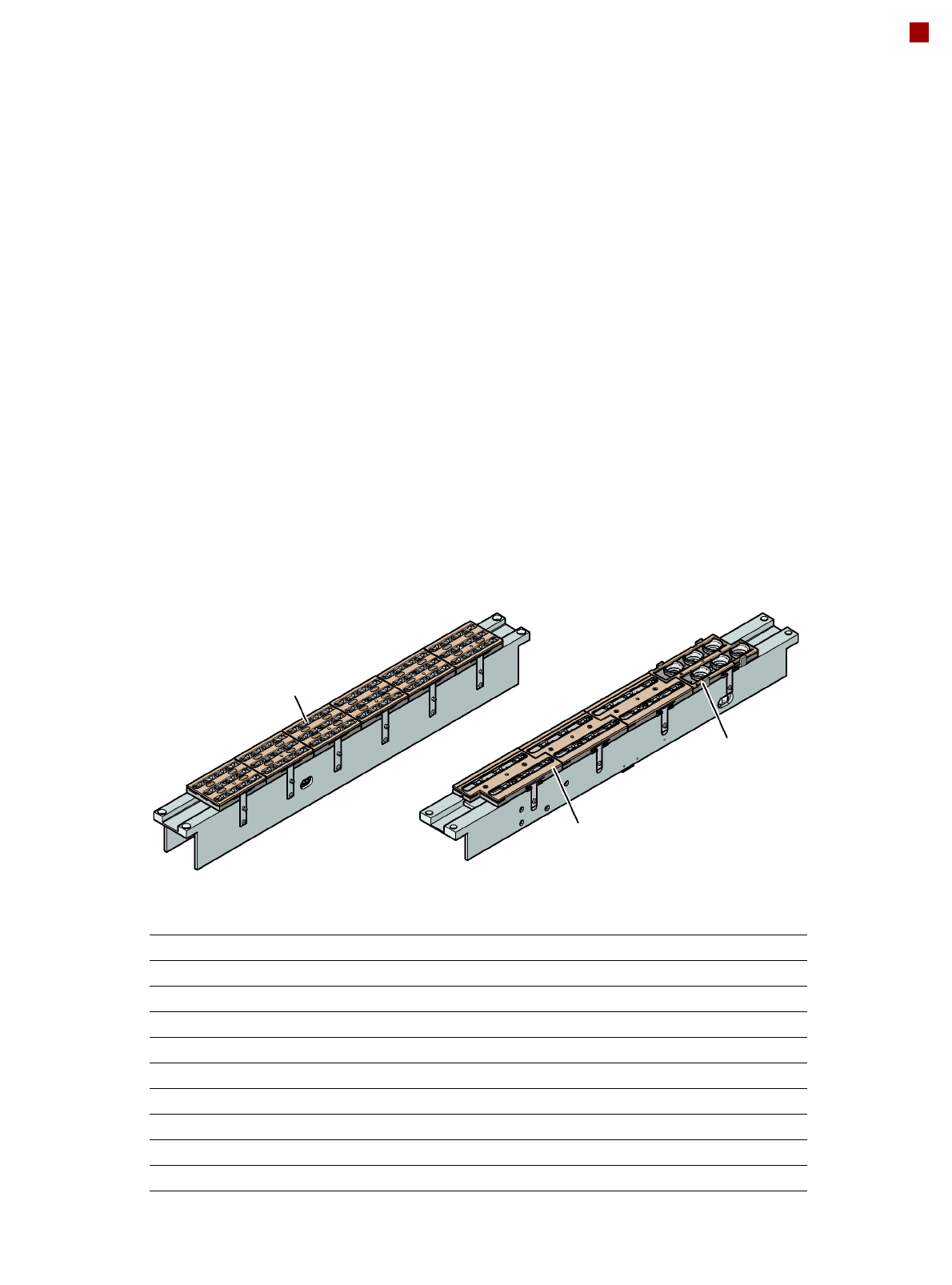
Magazine for 12
type 9xx nozzles
Nozzle changer for the
6-nozzle Collect&Place head (NCH6)
Magazine for 6
type 9xx nozzles
Magazine for 6
type 8xx nozzles
Description
Nozzle changers increase
the flexibility of placement
heads when processing dif-
ferent components. The noz-
zle configuration can be
quickly modified for new
placement jobs. Exactly
defined positions and the
perfect seating of the nozzle
in the garage guarantee min-
imal radial eccentricity at the
placement head.
Two nozzle changers can be
installed for the 6-nozzle or
12-nozzle Collect&Place
heads (C&P6 or C&P12):
Location 1: 1 nozzle changer
(NCH6 or NCH12)
Location 2: 1 nozzle changer
(NCH6 or NCH12)
Nozzle changer for the
12-nozzle Collect&Place head (NCH12)
Nozzle changer for the 12-nozzle Collect&Place head
Dimensions (length x width x height) 565 x 63 x 78 mm³
Number of magazines min. 1 / max. 6, each with 12 nozzle holders
Nozzle types 9xx
Compressed air connection 0.48 MPa (4.8 bar)
Nozzle changer for the 6-nozzle Collect&Place head
Dimensions (length x width x height) 565 x 69 x 87 mm³
Number of magazines min. 1 / max. 4, each with 6 nozzle holders
Nozzle types 8xx, 9xx
Compressed air connection 0.48 MPa (4.8 bar)
14
PCB Conveyor
Overview
Conveyor principle
If the board has reached the
placement area and passed
a light barrier, it is braked. An
additional laser light barrier
determines the position of
the board. As soon as the
circuit board has reached its
target position, the conveyor
belt is stopped and the board
is clamped from below. The
placement process then
starts immediately. Move-
ment and clamping of the
PCBs are monitored.
The conveyor can be easily
matched to many different
PCB widths. The fixed con-
veyor rail may be located on
the left or right for both the
flexible dual conveyor and
the single conveyor.
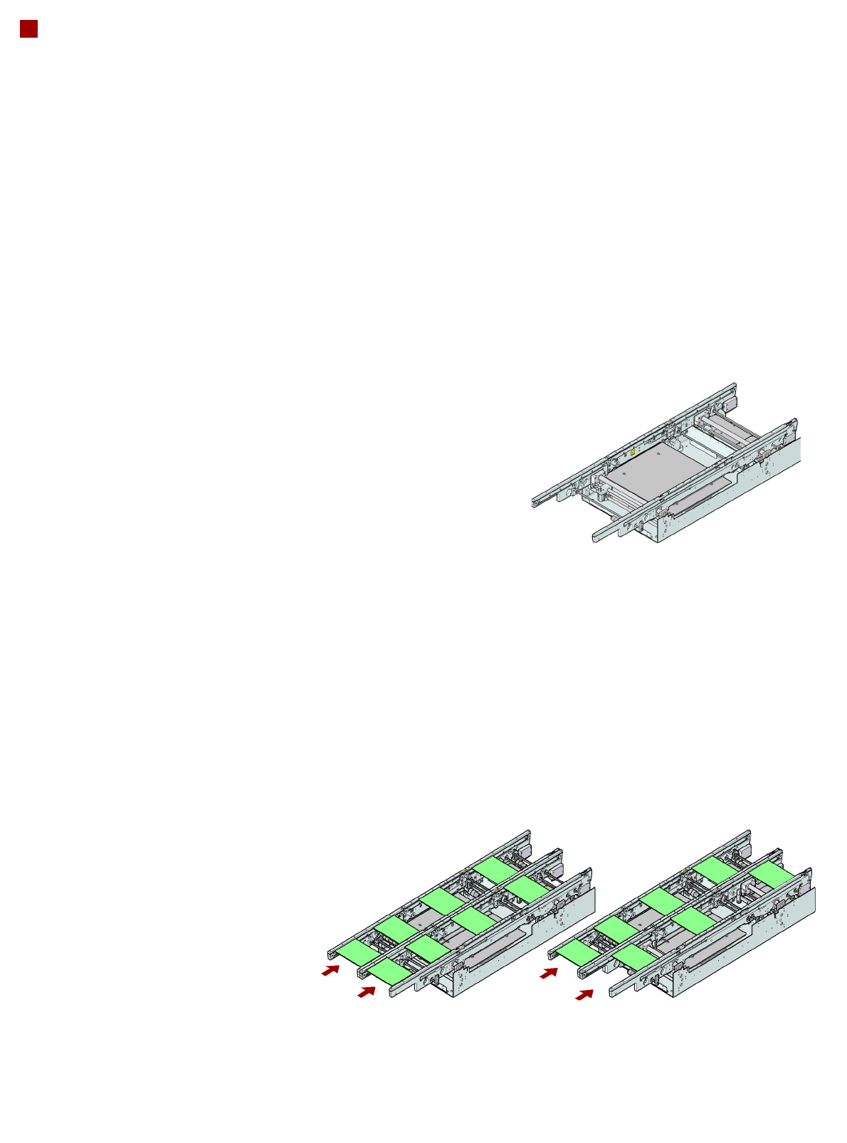
Single conveyor
On the single conveyor,
PCBs are moved one after
the other into the placement
machine and placed on a
conveyor track.
Flexible dual conveyor
To keep the range of PCBs to
be processed as wide as
possible - whilst maintaining
maximum productivity - the
flexible SIPLACE dual con-
veyor allows you to choose
between single conveyor
mode and dual conveyor
mode.
In dual conveyor mode, two
PCBs are moved into the
placement machine and
placed either simultaneously
(synchronous operation) or
alternately (asynchronous
operation).
In synchronous mode, two
PCBs are moved into the
placement position at the
same time. They are pro-
cessed as a common panel.
This allows the top and bot-
tom of PCB to be processed
on the same line and, for
products with very different
components to be placed,
the common optimization of
all the components to be
placed on both PCBs makes
it possible to increase output.
In asynchronous mode,
only one PCB in a transport
track is processed. At the
same time, another PCB in
the second transport track is
moved into the placement
position. This saves the full
conveying time of one PCB,
thus considerably increasing
performance, particularly for
PCBs with a short cycle time.
The placement process
starts as soon as one PCB
is transported into the
processing area.
Conveyor buffer
SIPLACE PCB conveyors
have buffer zones. If shorter
waiting times occur in a
placement area (due to lon-
ger cycle times in the oven,
for example), the down-
stream placement areas can
continue to work since the
unaffected area can easily
access the PCB that is wait-
ing in the buffer zone. This
increases the true output of
the placement line.
Flexible dual conveyor:
synchronous mode
Flexible dual conveyor:
asynchronous mode
Single conveyor