SIPLACE D2I 规格说明书英文版 - 第22页
22 Digital Vision System The digital SIPLACE vision system guarantees extremely fa st and relia ble component recognitio n, while being very simple to use. The sy stem identifies each individu al component from its shape…
21
Component Feeding
Alternative SIPLACE Feeder Modules
Technical data
Bulk case feeder modules
a
Packaging form
Feeding rails
Location
Bulk case
Chip 0402 component height:
0.5 mm
Chip 0603 component height:
0.8 mm
1
Linear vibratory feeder, type 3
Packaging form
Number of tracks and width
Location
Stick steel magazines
3 x 9.5 mm
2 x 15 mm
1 x 30 mm
1
Dip module takes up 3 locations of a
3 x 8 mm S feeder module
a) Fiducial for feeder module position recognition
Description
The SIPLACE bulk case
feeder module processes
bulk cases on two tracks. It
feeds rectangular and round,
passive components. The
PCB magazines (bulk cases)
are simply replaced for refill-
ing - without stopping the
machine.
The module essentially con-
sists of the basic element
plus two feeder rails and
PCB magazines to suit the
component type and height.
The components are sepa-
rated and fed along the rails
by compressed air.
The principle of the fixed
component table has proven
its worth, even when bulk
cases are used: the vibra-
tions that can occur with
other placement machine
concepts can have a highly
detrimental effect on the
component quality due to
abrasion, for example.
Even with stick magazines,
the stationary component
supply has significant advan-
tages: the universal vibratory
stick feeder can be topped up
during placement.
The dip module is suitable for
dip-fluxing flip-chips, CSPs
(chip-scale/size packages)
and for wetting flip-chip
bumps with isotropic, con-
ductive adhesive.
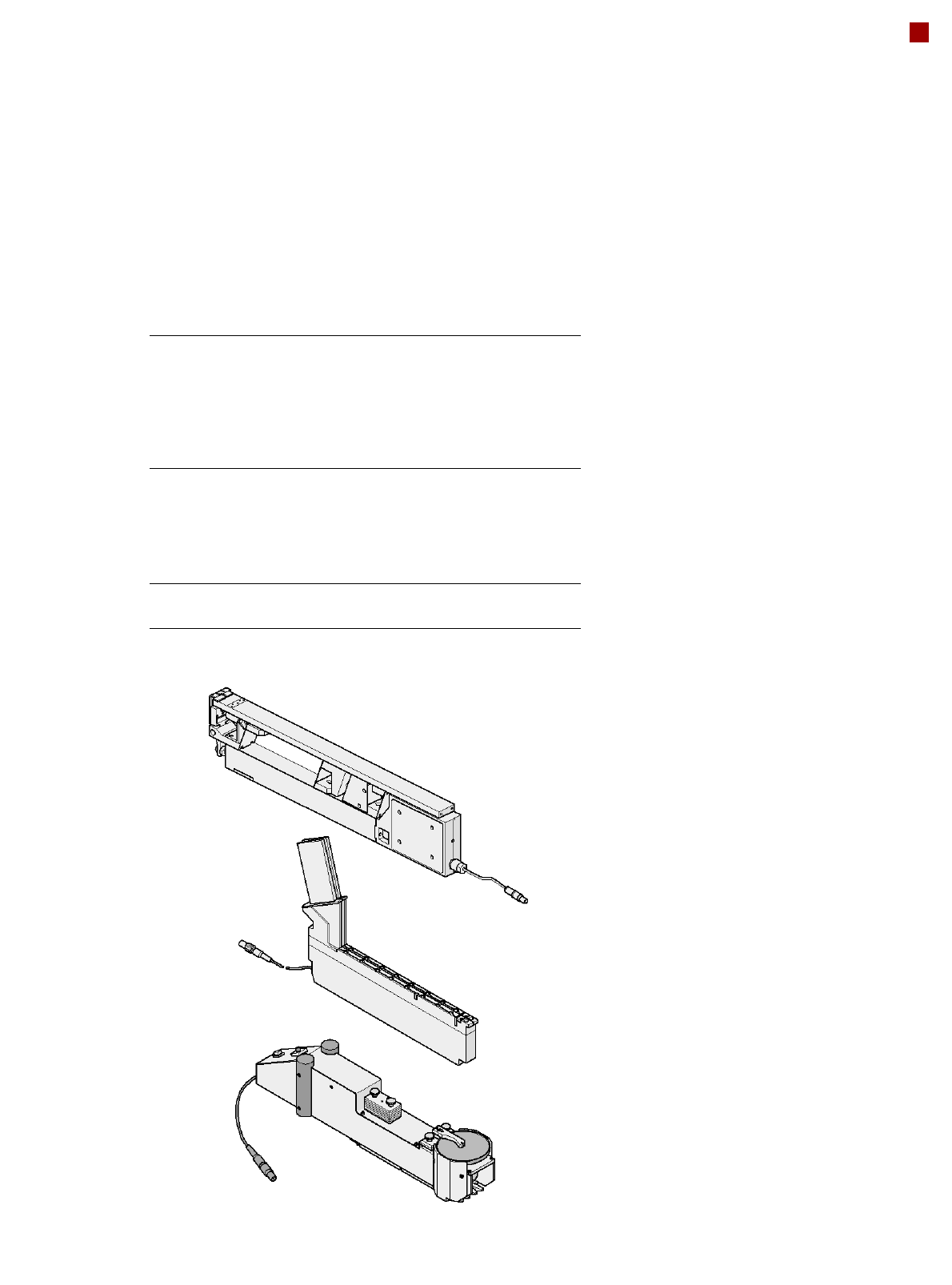
Bulk case feeder module
Linear vibratory feeder, type 3
Dip module

22
Digital Vision System
The digital SIPLACE vision
system guarantees
extremely fast and reliable
component recognition,
while being very simple to
use. The system identifies
each individual component
from its shape and color.
Even complex component
shapes, such as flip-chip or
CCGA are detected
extremely reliably.
The system is not only used
in the placement head cam-
eras; it can also be found in
the PCB camera. As well as
ensuring that components
are detected accurately, it
also ensures reliable recog-
nition of the ink spots and
PCB fiducials.
The benefits at a glance:
• Extremely fast and reliable
component recognition
• Shortest cycle times
• Robust measurement with
reference to the shape
and color
• Straightforward program-
ming
• Offline programming of
component shapes
• Rapid introduction of new
products (NPI)
• Open architecture allows
you to quickly adapt to
new requirements
• Optimum placement
results through individual
measurement of each
component
Digital vision cameras
12-nozzle Collect&Place head camera for 01005, type 30
12-nozzle Collect&Place head camera, type 28 (standard)
6-nozzle Collect&Place head camera, type 30
PCB camera, type 34
Examples of digital vision system analysis times
01005 9 ms
PLC44 17 ms
BGA 225 balls 18 ms
23
Digital Vision System
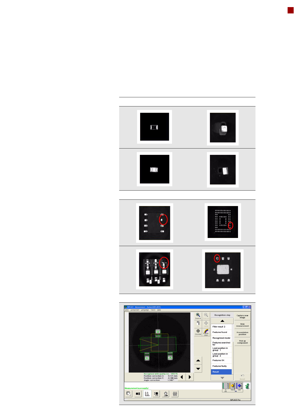
Checking the Component Quality
SIPLACE Vision algorithms
help with the detection of
• flipped components
• upright components
• poor component quality
The digital SIPLACE Vision
System automatically saves
the last 500 images of com-
ponents that were identified
as "bad". SIPLACE users
can then easily demonstrate
poor component quality.
The benefits at a glance:
• Maximum placement qual-
ity
• High first pass yield
• Reduced operating costs
Flipped components Upright components
Poor component quality
Vision Teach menu at the station