YSD_Users_E.pdf - 第127页
3-14 3 Q & A 4.1.2 Making the settings Use the following procedure to make the settings. 1 Enter the detection angle. In the VmSpec window that appears with the [Machine] button, open “Setting” – “Mechanical” – “Posi…
3-13
3
Q & A
4
Adjust the sensor level when the liquid still remains.
1. Set the syringe full of liquid into the head assembly.
c
CAUTION
If the product label affixed to the syringe is large so that it covers the lower part of the syringe, peel it off from the lower
half of the syringe.
If the product label covers the lower part of the syringe, the low-liquid sensor cannot detect whether adhesive has run
out or not.
2. Allow the sensor beam to strike the syringe.
The holder in which the syringe is set contains 4 openings. Rotate the R-axis so that the sensor faces
the opening where the lowest value is obtained.
3. Press the Auto SET button on the amp and check that the calibration indicator turns off.
5
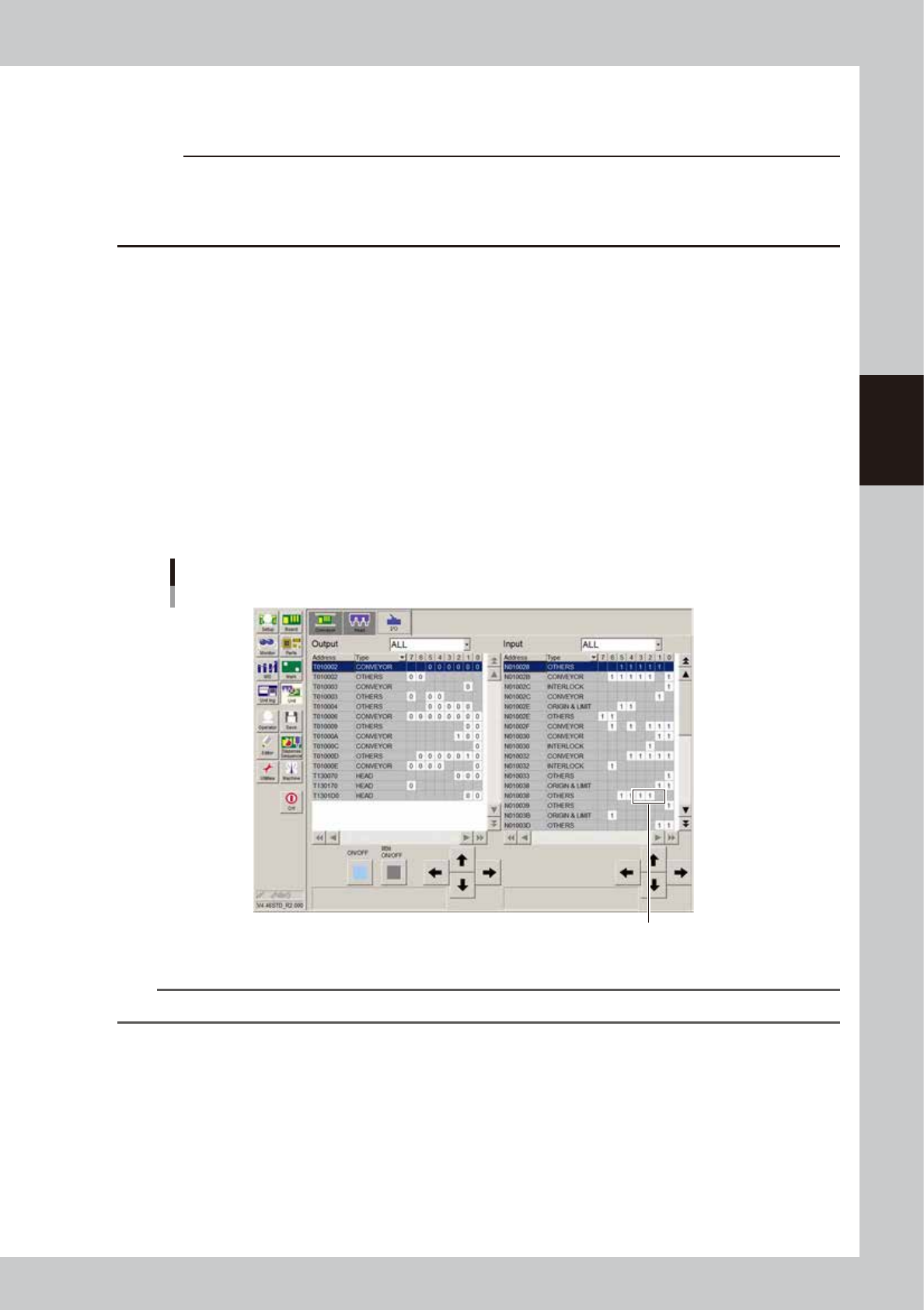
Check the sensor ON/OFF operation.
1. Open the [Unit]-[I/O] tab.
2. Move the piston of the empty syringe up and down across the sensor optical axis, and check that
the I/O monitor for the sensor switches as follows.
Head 1 :N1301001
Head 2 :N1301002
Head 3 :N1301003
When liquid is detected (liquid remains) :1
When no liquid is detected (no liquid remains) :0
Sensor ON/OFF check
Check here.
64301-N7-00
n
NOTE
• When using the low-liquid sensor, set the maximum liquid amount for the dot station to "0".
3-14
3
Q & A
4.1.2 Making the settings
Use the following procedure to make the settings.
1
Enter the detection angle.
In the VmSpec window that appears with the [Machine] button, open “Setting” – “Mechanical” –
“Position” and enter the angle in “Wait Point – R (deg)”. In most cases, enter “-114” deg. (The remaining
liquid amount will be detected at angles of -114, -24, 66, and 156.)
Entering the detection angle
Enter detection angle.
64302-N7-00
n
NOTE
If the remaining liquid amount cannot be detected correctly with the “-114” setting, check to find the angle that
allows correct detection.
Rotate the R-axis by hand to align it with the position where all sensors can detect the remaining liquid. Then open the
[Unit] – [Head] – [Move Axis] screen, check the R-axis coordinate displayed on the [ZR] tab, and enter it as the
detection angle.
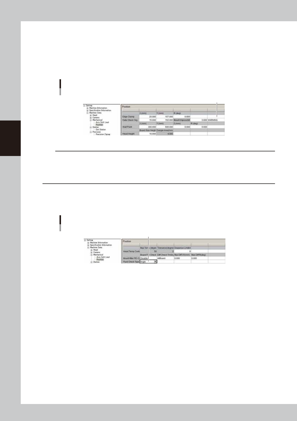
2
Set the detection method.
In the VmSpec window, open “Setting” – “Mechanical” – “Position” and set “Fluid Check Type” to
“Angle”.
Setting the detection method
Set to “Angle”.
64303-N7-00

Chapter 4 Making the dispensing stable
Contents
1. Making the dispensing stable 4-1
2. Dispensing test function 4-2
2.1 Overview 4-2
2.2 Performing a dispensing test 4-3
2.3 Starting a dispensing test during automatic operation 4-6
3. Creating the predispensing information 4-8
3.1 Using the dispense correction function 4-8
3.1.1 Enabling each setting 4-10
3.1.2 Creating the predispense parameters 4-12
3.1.3 Creating the mark data for dot recognition 4-14
3.1.4 Checking the dispensing amount on the dot station 4-20
3.1.5 Checking the dispensing amount on the board 4-22
3.1.6 Creating the dispense correction (map) 4-23
3.1.7 Setting the calculation type 4-27
3.1.8 Checking that each setting is consistent 4-33
4. Position correction dispense function 4-34
4.1 Overview and item restrictions 4-34
4.2 Setting method 4-35
4.3 Machine data setting 4-36
5. Dot station (option) 4-37
5.1 Dot station setup 4-37
5.1.1 Setting the dot station function 4-38
5.1.2 Entering the pre-dispensing position 4-39
5.1.3 Setting the dot station data 4-40
5.2 Setting the board information 4-42
5.3 Dispense correction limit check 4-44
5.3.1 Correction amount calculation 4-44
5.3.2 Setting method 4-47
5.4 Dispense correction retries 4-48
5.4.1 Setting method 4-50
6. Editing a dispense sequence 4-51
6.1 Performing a predispensing test 4-51
6.2 Editing the dispense sequence 4-51
7. Checking/correcting dispensing positions 4-55