YSD_Users_E.pdf - 第133页
4-5 4 Making the dispensing stable • Method Shows the chec k mode specified in the mark information. (Area/Peri., RoundLev el, Matching) • Area (mm2) (red when in error) Shows the area (mm2) of each dot. (Difference from…
4-4
4
Making the dispensing stable
1. Head Select
Select the head to use for dispensing and recognition. (Head 1, Head 2, Head 3, All)
Default setting
“All” when started from the Setup screen
The head that failed recognition when started from automatic operation
2. Conveyor Out
Carries out the board from the machine.
3. Conveyor In
Carries in a board and clamp it in the work position.
4. MarkAdj
Pressing this button performs a trace check for the selected row. The Mark Adjust window appears only when “Yes” is
selected. However, when all heads have been used to check the correction amount, only the last head is used for trace.
Operation is possible after the recognition results are displayed in the window.
5. Execute
Performs recognition and dispensing by referring to the data on the head selected in the predispense information.
6. Clear Results
Clears the recognition results displayed in the window.
7. Close
Clears the recognition results and closes the window.
TIP
The [Conveyor Out] and [Conveyor In] buttons can be used when the predispensing setting is “Execute” (on board)
and the test was started from the Setup screen.
3
Check the recognition results of the dispensing test.
If an error is found in the recognition results, adjust the air pressure and then press the [Execute] button
again.
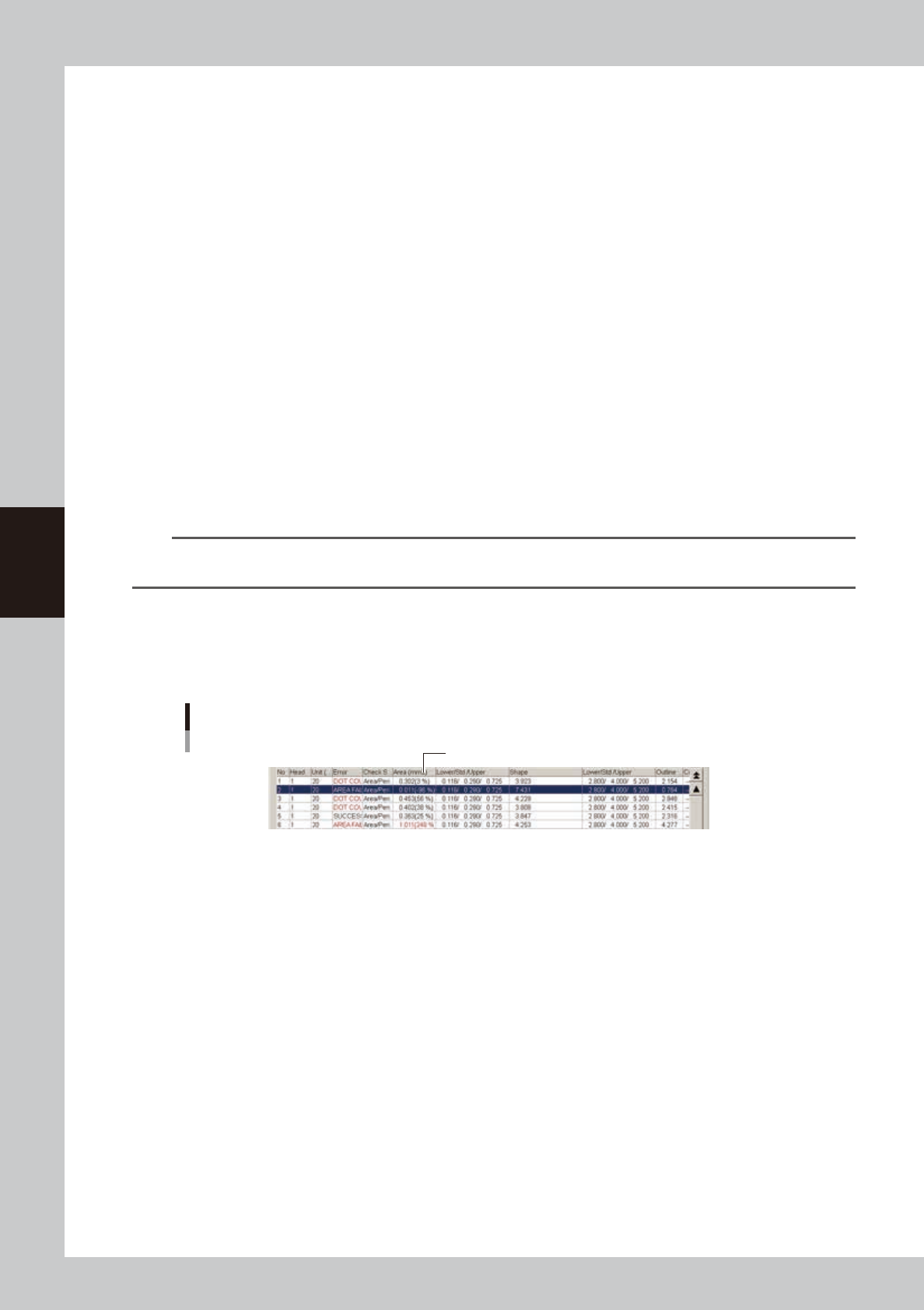
Adjust the air pressure so that the tolerance for “Area (mm2)” is within ±20%.
Dispensing test recognition results
Adjust air pressure so that tolerance is within ±20%.
64402-N7-00
• No.
Shows sequential numbers for recognition results.
• Head
Shows head numbers.
• Liquid amount
Shows the dispensing liquid amount.
• Error (red when in error)
Shows recognition results.
SUCCESS : Successfully recognized.
DOT COUNT FAILURE : Recognized, but the number of recognized dots does not match.
AREA FAILURE : Failed to recognize due to out of the area tolerance range.
SHAPE FAILURE : Failed to recognize due to out of the shape tolerance range.
OTHER FAILURE : Errors other than above

4-5
4
Making the dispensing stable
• Method
Shows the check mode specified in the mark information. (Area/Peri., RoundLevel, Matching)
• Area (mm2) (red when in error)
Shows the area (mm2) of each dot. (Difference from standard area [%] = (Area – Standard area) / Standard area)
• Lower limit / Std. / Upper limit
Shows the lower and upper limits calculated from the standard area and area tolerance.
Lower limit = Standard area × (1 – Area tolerance / 100)
Upper limit = Standard area / (1 – Area tolerance / 100)
When the area tolerance is 100: (0.000 / Standard area / ----)
c
CAUTION
The calculation formula differs from that for normal fiducial mark recognition.
• Shape (red when in error)
Shows the following calculated values. The displayed item differs depending on the “Shape Check” setting.
Area/Peri. : Perimeter /
√
Area
RoundLevel : Radius of inscribed circle / Radius obtained from inscribed and circumscribed circles / Radius of
circumscribed circle
Matching : Area ratio of irregularities (concavities/protrusions)
• Lower limit / Std. / Upper limit
Shows the following calculated values. The displayed item differs depending on the “Shape Check” setting.
Area/Peri. : Upper limit calculated from the shape constant and shape tolerance.
Lower limit = Shape constant × (1 – shape tolerance / 100)
Upper limit = Shape constant × (1 – shape tolerance / 100)
RoundLevel : Upper and lower limits calculated from inscribed and circumscribed circles and shape tolerance
Radius obtained from inscribed and circumscribed circles × (1 – shape tolerance / 100)
Upper limit = Shape constant × (1 - shape tolerance / 100)
Matching : Area ratio of irregularities (concavities/protrusions) is within shape tolerance (upper limit only) <
Shape tolerance
• Perimeter
Shows the perimeter of each dot.
• RoundLevel
Shows the roundness of each dot when the “Shape Check” setting is “RoundLevel”.
• Radius (mm)
Shows the radius of each dot when the “Shape Check” setting is “RoundLevel” or “Matching”.
RoundLevel : Radius of each dot, obtained from inscribed and circumscribed circles
Matching : Radius of each dot, obtained from area.
• X, Y
Shows the XY coordinates specified in the predispense information.
• dX, dY
Shows the difference from the recognized coordinates in the X and Y directions.
4-6
4
Making the dispensing stable
2.3 Starting a dispensing test during automatic operation
If a dot recognition error occurs during predispensing, perform a dispensing test with the following procedure.
Dispensing test cannot start unless the machine is equipped with a dot station or the predispensing is set to “On
dot station”.
Flowchart when error occurs
Predispense
Start operation
Dot dispensing
Perform
dispensing test
Select action
(dispensing test)
Select action
(retry)
Clear error
Adjust
air pressure
Check recognition
results
Recognition error
NG (fail)
OK (pass)
63401-N7-00
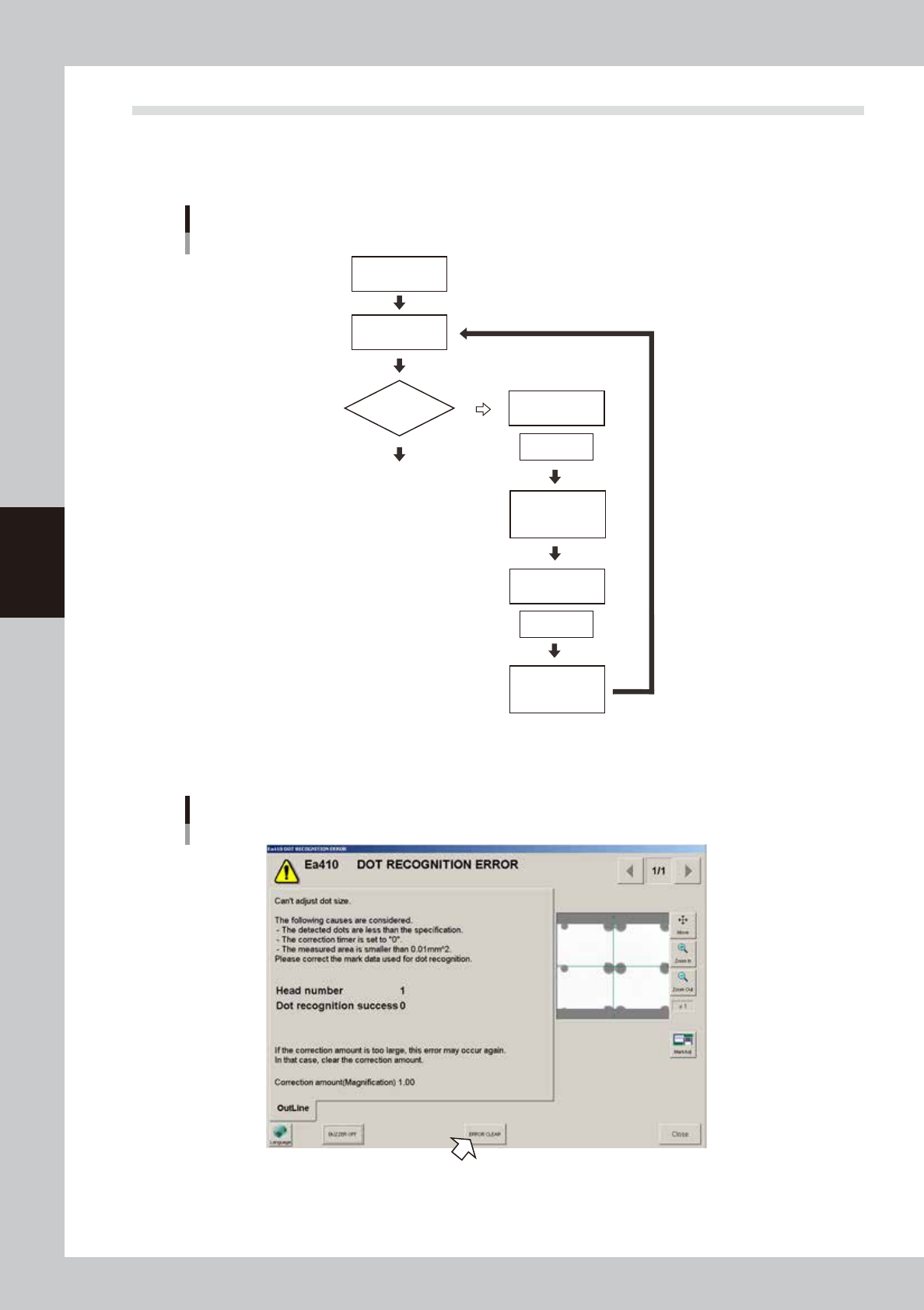
1
Press the [ERROR CLEAR] button.
Dot recognition error
64403-N7-00