YSD_Users_E.pdf - 第190页
5-1 5 Creating the board data 1. Over view The board data is indexed by each individual board name. Each board type consists of various information and parameters as shown below , which can be selected or checked with th…

5. Creating the component information 5-35
5.1 Creating procedure 5-36
5.2 Chip components 5-37
5.2.1 Basic parameters 5-37
5.2.2 Shape parameters 5-38
5.2.3 Dispense parameters 5-39
5.3 IC components 5-40
5.3.1 Mini-mold transistors and SOT 5-40
5.3.2 SOP components 5-43
5.3.3 QFP components 5-45
5.4 Ball lead components 5-47
5.4.1 BGA components 5-47
5.5 Connector components 5-48
5.5.1 Connectors 5-48
6. Creating the mark information 5-51
6.1 Creating procedure 5-52
6.2 Basic parameters 5-53
6.3 Shape parameters 5-54
6.4 Vision parameters 5-56
6.5 Mark Adjust mode 5-58
6.6 Pattern matching 5-62
6.6.1 Pattern registration 5-63
6.6.2 Using the data for pattern matching 5-67
7. Creating dot dispense information 5-68
7.1 Dispense distribution 5-68
7.2 Editing the dot dispense information 5-73
8. Height correction (option) 5-74
8.1 Creating the board data for height correction 5-74
8.2 Height correction distribution 5-76
5-1
5
Creating the board data
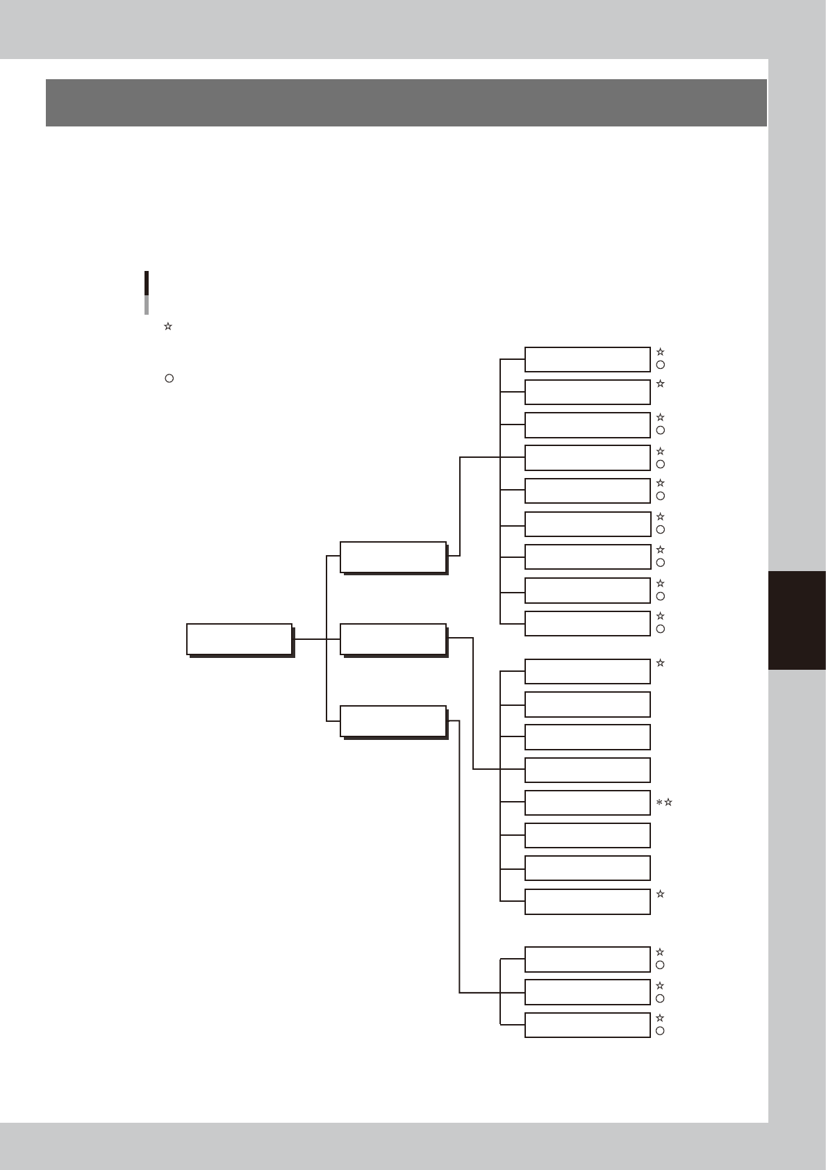
1. Overview
The board data is indexed by each individual board name. Each board type consists of various information
and parameters as shown below, which can be selected or checked with the menu button and tab on the
operation screen. This section describes basic methods for creating board data so that you will understand
what data is needed for what item. After you have obtained a complete understanding of these methods,
begin actual work according to the desired method.
The figure below shows the parameters necessary to create board data from YAMAHA mounter data or CAD
data and also by manual input.
Board data structure
Board name Parts
Basic
Vision
Shape
Mount
Pick
Tray
Option
Dispense
Shape
Vision
Basic
Mount
Board
Parameters created from YAMAHA mounter data or CAD data
* Parameters when solder is used
Parameters created by manual input
Not used
Not used
Not used
Not used
Not used
Various parameters
Fiducial
Badmark
Offset
Pre-dispense
Dot Dispense
Height offset
Position correction dispensing
Board
Mark
63500-N7-00
5-2
5
Creating the board data
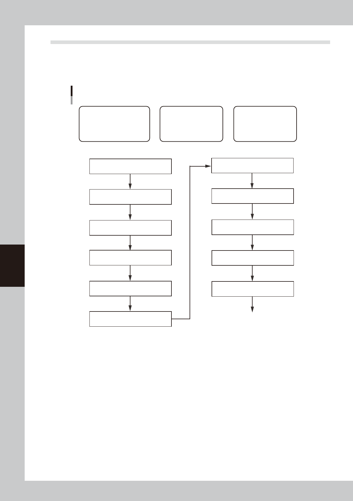
1.1 Creating the board data from mounter data
This section describes how to create dispenser board data using YAMAHA mounter board data. Follow the steps
below to create board data using the data that contains mount information and parts information of parts
requiring dispensing tasks. Since the title of each step is identical with the heading of each section in this
manual, refer to the table of contents to find the information on the steps you want to know.
Basic procedure for creating data from mounter board data
[1] Chapter 7, section 3.1
“Converting VIOS data into YGX data”
* When board data is not YGX
[1] Chapter 8, section 1.2
“Copying and moving the board data”
[2] Chapter 4, section 3
“Creating the predispense information”
[3] Chapter 5, section 5
“Creating the parts information”
Create parts data for dispensing
[3] Chapter 5, section 7.1
“Dispense distribution”
[1] Data related to board
• Basic information on nozzles,
temperature setting, etc.
• Information necessary to clamp
board and make corrections
[2] Predispensing operation
Information necessary to
ensure stable dispensing
[3] Dot dispensing operation
Information necessary to
dispense on board
[1] Chapter 5, section 4.1
“Board parameters (Board)”
[3] Chapter 7, section 4.2
“Deleting the dispensing points”
* When mount data contains parameters not requiring dispensing
[1] Chapter 5, section 3.1
“Nozzle information (Setup)”
[1] Chapter 5, section 3.2
“Temperature setting (Setup)”
[1] Chapter 5, section 6.5
“Mark Adjust mode”
[2] Chapter 4, section 4
“Position correction dispense function”
Perform dispensing test
63551-N7-00