YSD_Users_E.pdf - 第205页
5-16 5 Creating the board data 4.2 Mount parameters T his section explains how to set mount parameters such as mounting position data and component number . Mount parameters are used for automatic creation of dispense da…

5-15
5
Creating the board data
I: Unloader Count Max.
Specify the number of boards that can be stored in one rack of the unloader. When the specified number of boards has
been produced and transferred out into the unloader, the machine stops transfer of the production board until the
unloader replaces the rack. If this is set to “0”, the machine continues production without checking the number of boards
transferred out into the unloader. Enter “0” in the following cases.
• The unloader being used provides a rack switching signal output.
• This setting data is to be used for the machine just before reflowing.
J: Board Fix Device
Set to "Edge Clamp"in most cases.
Board is clamped on the conveyor with the edge clamps and push-up pins.
K: Pre-Fix Timer
The machine begins to clamp the board immediately after it passes above the board sensor installed just before the main
stopper. The optimum clamping timing (delay time with respect to the sensor detection) depends on the board size and
conveyor speed. Use this parameter to set the clamp timing (0.0 to 1.9 sec.).
L: Trans Height
After components are mounted, the machine permits the conveyor to carry out the board when the push-up unit is
lowered. If components have already been mounted on the reverse side of the board, the push-up unit must be lowered
sufficiently to avoid interference from push-up pins with those components. This parameter specifies the height of the
push-up unit at which the conveyor is allowed to carry out each type of board. Enter the distance in millimeters from the
point where the push-up unit is raised to clamp the board. This distance can be 5 to 30 mm.
M: Conveyor Timer
Set to “0.0” sec. for normal shape boards. If specially configured boards (for example, boards with cutout parts or
through-holes) are used and the exit sensor cannot detect them reliably, try setting this timer in the range of 0.0 to 9.9
sec. The conveyor motor continues turning for the specified time even after the board sensor turns off.
N: Alignment (Not used with this machine.)
O: Vacuum Check (Not used with this machine.)
P: Retry Sequence (Not used with this machine.)
Q: Precede Pick
Set to “Use” in most cases.
S: Dot Checking
Set to “Use” to perform predispensing.
When set to “Use”, the image of the predispensed dot is recognized to check the dispensing liquid run-out, nozzle
clogging, cobwebbing, etc. according to the mark number specified in advance by the predispense data.
T: Refresh Dispense
Set this parameter when pre-dispensing adhesive on the dot station (option) to refresh the dispense dot size.
For details of the setting method, refer to "5.1.1 Setting the dot station function" in Chapter 4.
X: Conveyor Motor Speed (%)
Set the conveyor motor speed (Board transfer speed). With respect to the machine setting speed, the conveyor speed can
be adjusted to 50% on the plus side and 90% on the minus side in 10% steps.
U: Conveyor Transfer Way
The conveyor transfer method can be set for each board data. Select the desired method from among “Machine Setting”,
“Normal” and “Fast”.
• Machine Setting
This uses the transfer method that is specified by the machine setting (VmSpec).
• Normal
When dispensing on a board is finished, the finished board is unclamped and starts being transferred to the conveyor
exit. When the finished board has passed the WorkOut sensor on the conveyor, another board at the standby position
is conveyed into the work position.
• Fast
When dispensing on a board is finished, the finished board is unclamped and starts being transferred to the conveyor
exit. When the finished board is detected by the WorkOut sensor on the conveyor, another board at the standby
position is conveyed into the work position. The main stopper rises when the finished board has passed the WorkOut
sensor.
5-16
5
Creating the board data
4.2 Mount parameters
This section explains how to set mount parameters such as mounting position data and component number.
Mount parameters are used for automatic creation of dispense data.
c
CAUTION
When mount parameter data is copied from the mounter, delete the mount data that is not needed for dispense data.
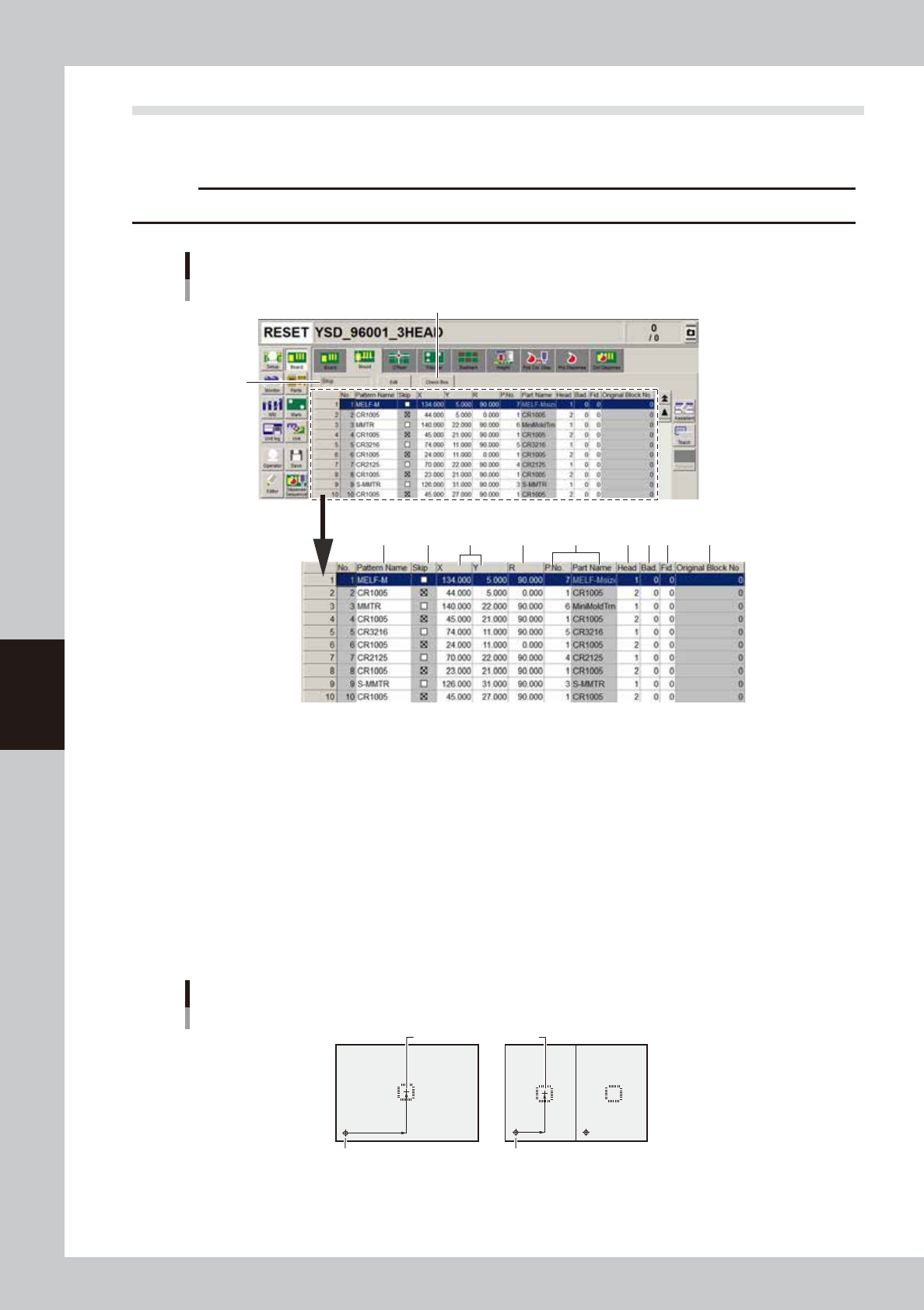
1
32 4 5 87 9 10
11
6
Mount parameter screen
64506-N7-00
1. Execute/Skip
Pressing the [Edit] button allows changing this setting, but set to "Skip" in this machine.
2. Pattern Name
Enter the land pattern name or symbol (ex., R23, U12, etc.) printed on the board.
3. Skip
Place a checkmark when not mounting a component at this mount point.
4. X, Y
For single boards, enter the XY coordinate data of the center of the mounting position relative to the board origin. For
multi-block boards (multi-board panels), enter the position data relative to the reference block. You can also use the
teaching function to enter the XY coordinate data as explained below.
Center of mounting position
Mounting position relative to board origin
Board origin Block repeat No.1
Block 1 Block 2
63502-N7-00
5-17
5
Creating the board data
Teaching method for different components
Component type
Teaching method
Teaching point
CHIP
1 or 2-point input
Tr.
1 or 3-point input
SOP
2 or 4-point input
QFP
2 or 4-point input
:
Teaching point
63503-N7-00
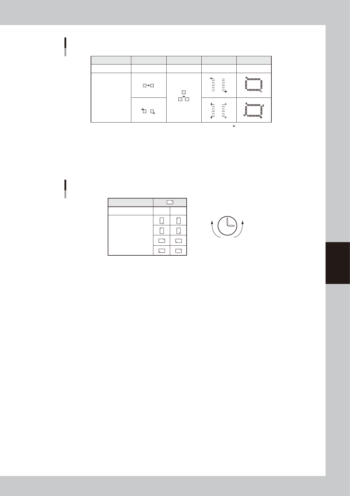
5. R
Enter the angle through which the component must be rotated after recognition before it is mounted on the board. When
the pickup angle is 0 deg., enter the rotating angle from the loading position, with the counterclockwise direction
specified as a plus value when viewed from above. When the pickup angle is 90 deg. or -90 deg., see the table below.
Mounting angle
Loading position
Pickup angle 90˚ -90˚
Mounting angle 0˚
180˚
90˚
-90˚
Clock
PlusMinus
63504-N7-00
6. P. No., Part Name
Enter the component number (data No. in the component information) to be mounted. The component name will be input
automatically according to the component number.
7. Head
Enter the head number to be used for mounting.
8. Bad (badmark)
Enter the number of the local badmark to be used for this mount data. Note that this setting is valid only when necessary
data is input on the Badmark tab screen.
Enter “0” here when not using the local badmark function.
9. Fid. (Fiducial mark)
Enter the fiducial mark number (point, local or 4-point fiducial) to be used for this mount data. Note that this setting is
valid only when necessary data is input on the Fiducial tab screen.
Enter “0” here when not using the fiducial function.
10. Original Block No.
Shows the block No. that was automatically allocated to each block after block distribution (with note data) was
performed. For details on block distribution (with note data), refer to "2.2.1 Block offset distribution" in Chapter 7.
11. [Check Box] button
Pressing this button allows the "Skip" column to be edited. Pressing the [Check Box] button again grays out the "Skip"
column and making changes is no longer possible.