YSD_Users_E.pdf - 第207页
5-18 5 Creating the board data 4.3 Of fset parameters Selecting the [Offset] tab opens the screen for setting the offset data for each bloc k relativ e to the reference block of a multi-bloc k board consisting of two or …
5-17
5
Creating the board data
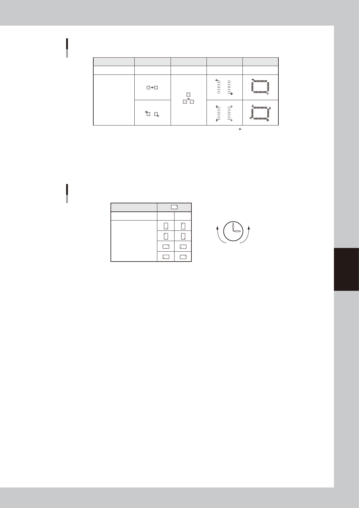
Teaching method for different components
Component type
Teaching method
Teaching point
CHIP
1 or 2-point input
Tr.
1 or 3-point input
SOP
2 or 4-point input
QFP
2 or 4-point input
:
Teaching point
63503-N7-00
5. R
Enter the angle through which the component must be rotated after recognition before it is mounted on the board. When
the pickup angle is 0 deg., enter the rotating angle from the loading position, with the counterclockwise direction
specified as a plus value when viewed from above. When the pickup angle is 90 deg. or -90 deg., see the table below.
Mounting angle
Loading position
Pickup angle 90˚ -90˚
Mounting angle 0˚
180˚
90˚
-90˚
Clock
PlusMinus
63504-N7-00
6. P. No., Part Name
Enter the component number (data No. in the component information) to be mounted. The component name will be input
automatically according to the component number.
7. Head
Enter the head number to be used for mounting.
8. Bad (badmark)
Enter the number of the local badmark to be used for this mount data. Note that this setting is valid only when necessary
data is input on the Badmark tab screen.
Enter “0” here when not using the local badmark function.
9. Fid. (Fiducial mark)
Enter the fiducial mark number (point, local or 4-point fiducial) to be used for this mount data. Note that this setting is
valid only when necessary data is input on the Fiducial tab screen.
Enter “0” here when not using the fiducial function.
10. Original Block No.
Shows the block No. that was automatically allocated to each block after block distribution (with note data) was
performed. For details on block distribution (with note data), refer to "2.2.1 Block offset distribution" in Chapter 7.
11. [Check Box] button
Pressing this button allows the "Skip" column to be edited. Pressing the [Check Box] button again grays out the "Skip"
column and making changes is no longer possible.
5-18
5
Creating the board data
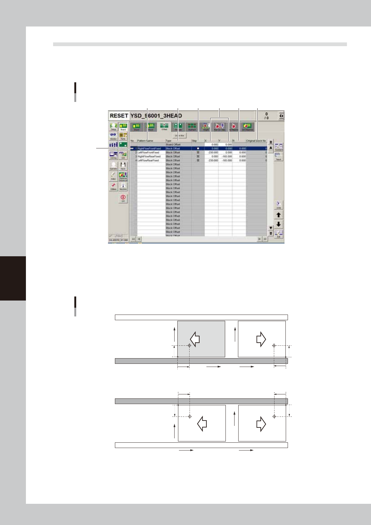
4.3 Offset parameters
Selecting the [Offset] tab opens the screen for setting the offset data for each block relative to the reference
block of a multi-block board consisting of two or more independent printed circuits of the same type. The XY
coordinates of the board origin are also specified here.
2
1
3 4 5 6 7
Offset parameter screen
64507-N7-00
1. Board Origin
In the top row of the offset data gird, enter the XY coordinates of the board origin.
For machines with the front conveyor rail fixed, the board origin is specified as X=0.00, Y=0.00, which is 5mm (X and Y
coordinates) away from the forward corner of the board on the front conveyor rail side.
5mm
5mm
X
Y
5mm
5mm
5mm
5mm
5mm
5mm
X
Y
X
Y
X
Y
Front conveyor rail fixed
Board origin
Rear conveyor rail fixed
Direction of
board flow
63305-N5-00
5-19
5
Creating the board data
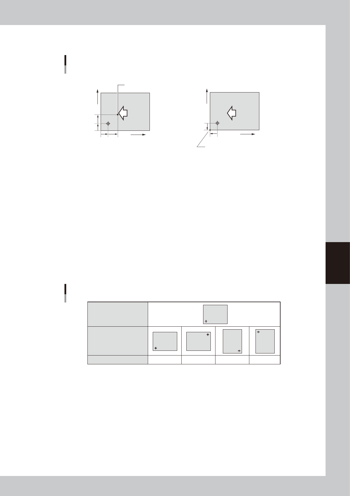
When setting the board origin at another position as shown below, enter the position relative to the coordinates
at X=5 mm and Y=5mm.
When setting the board origin
at this point, enter "X=7.00" and Y=7.00.
• Board origin ≠ Loce pin position
Board Origin
• Board origin ≠ Board corner
When setting the board origin at the corner of a
board in right-to-left flow (with the front rail fixed),
enter "X=-5.00" and Y=-5.00.
7mm
5mm
7mm
5mm
X
Y
Direction of
board flow
5mm
5mm
X
Y
Direction of
board flow
63506-N7-00
2. Pattern Name
Enter the block name.
3. Type
The board origin is specified on the top line, and block offset data on the second and subsequent lines.
4. Skip
Place a checkmark when not mounting components in this block.
5. XY
Enter the XY coordinates of the origin in each block relative to the board origin. You can use the [Teach] button to enter
the XY data or trace the specified data.
6. R
Enter the rotation angle of each block with respect to the reference block. You can use the [Teach] button to enter the R
data or trace the specified data.
Reference block direction
Block direction
R data
R data
0゚ 180゚ 90゚ -90゚
Block
Block
Block
Block
Block
63507-N7-00
7. Original Block No.
Shows the block No. that was automatically allocated to each block after block distribution (with note data) was
performed. For details on block distribution (with note data), refer to "2.2.1 Block offset distribution" in Chapter 7.