YSD_Users_E.pdf - 第218页
5-29 5 Creating the board data 4.6 Height correction parameters (option) T hese parameters are used to set the coordinates and method for making height measurement with the laser displacement meter . 1 5 2 3 Height corre…
5-28
5
Creating the board data
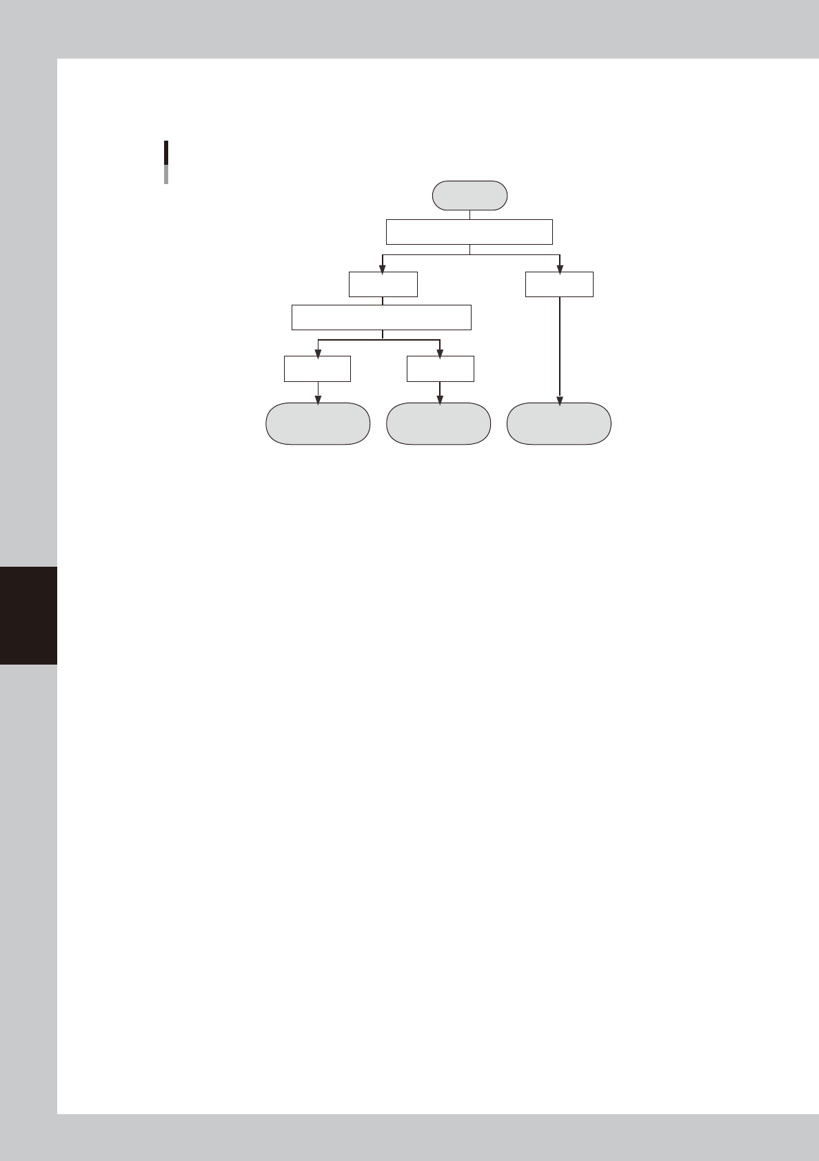
Badmark operation
The flow chart below shows a flow of badmark operation when a board badmark and block badmark have been set.
Operation
not performed for
the block
Operation
performed for
the block
Operation
performed for
all blocks
Start
Search board badmark
Detected Not detected
Search block badmark
Badmark operation flows
Detected Not detected
63315-N7-00
5-29
5
Creating the board data
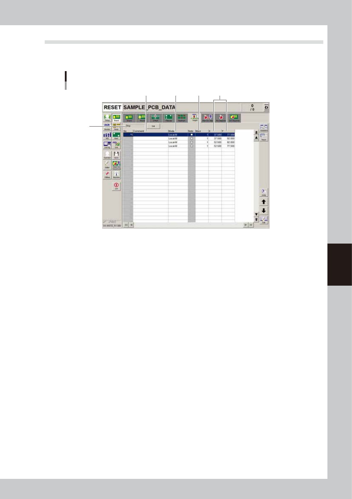
4.6 Height correction parameters (option)
These parameters are used to set the coordinates and method for making height measurement with the laser
displacement meter.
1
5
2 3
Height correction parameter screen
4
64513-N7-00
1. Comment
Enter a comment on the height measurement as necessary.
2. Mode
Make this setting according to the number of height measurement points.
• When measuring 1 point, set to "Local-M".
• When measuring 2 points to take an average, make the settings in 2 rows. Set the first row to "Local-M" and the second
row to "Local-S".
3. Mark
Enter the mark number used to correct the height of mark parameters.
4. X, Y
Set the X and Y coordinates relative to the board origin position.
5. Execute/Skip
Set whether to execute height correction. Height correction will not be performed when set to “Skip”.
5-30
5
Creating the board data
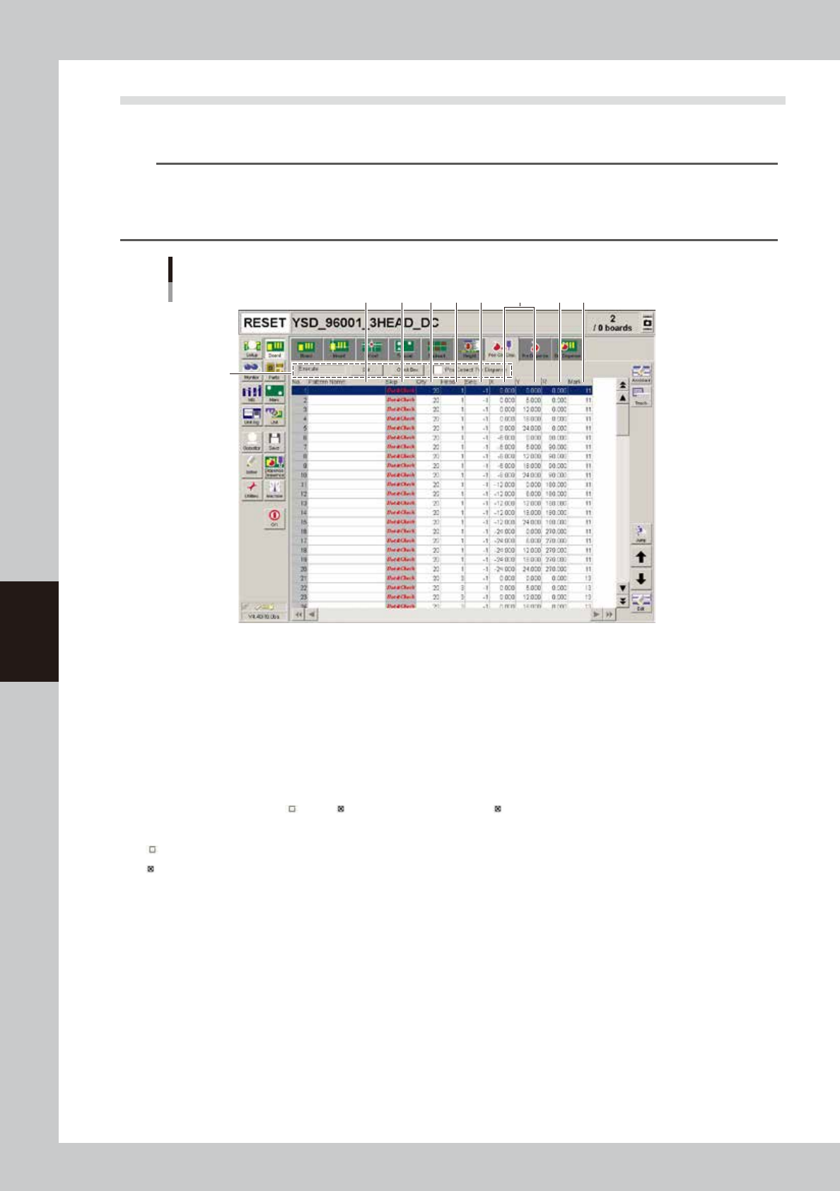
4.7 Position correction dispense parameters
These parameters are used for the position correction dispense function that corrects a deviation in the
dispensing position which may occur after a nozzle is changed, and makes the dispensing position stable.
n
NOTE
Copy the coordinates of the master board data (MCH_SETYP.ygx) as the coordinates for position correction dispense,
and enter the appropriate values for the liquid amount, sequence, and mark No. according to the pre-dispensing
conditions. If not using “pre-dispense”, perform a dispense test to create the liquid amount and mark data, and enter
the obtained values.
Position correction dispense parameter screen
2
1
3 7 94 5 6 8
64585-N7-00
1. Position correction dispense items
Specify these items to set whether to perform position correction dispense. To change the setting, press the [Edit] button
and select “Execute” or “Skip”. When the “Pos Correct Pre-dispense” check box is selected, dots will be pre-dispensed
before correcting the dispensing position.
2. Pattern Name
Enter the name used for position correction dispense. (This can be left blank.)
3. Skip
Set whether to perform position correction dispense at each dispensing position. Pressing each field in the “Skip” column
changes to “Dot&Check”, “ ” and “ ”. Set this column to “skip ( )” for the heads that are not used for dot dispensing.
“Dot&Check” : Dispenses dots and recognizes them to calculate the dispensing position correction amount.
“
” : Only dispenses dots.
“
” : Skips dispensing dots.
4. Qty
Enter the liquid amount according to the pre-dispensing conditions.
5. Head
Set the head number used for position correction dispense.
6. Seq.
Enter the value according to the pre-dispensing conditions.
7. X, Y
Use the XY coordinates of the master board data (MCH_SETUP.ygx) by copying them.
8. R
Use the R coordinate of the master board data (MCH_SETUP.ygx) by copying them.
9. Mark
Enter the number according to the pre-dispensing conditions.