YSD_Users_E.pdf - 第223页
5-34 5 Creating the board data 9. Fid. Set the fiducial No. to be used for dot dispense. If you are not using the fiducial function, set "0". 10. Bad Set the badmark No. to be used for dot dispense. If you are …
5-33
5
Creating the board data
4.9 Dot dispense parameters
This section explains how to set dot dispense parameters required when performing dispense using the
dispense head.
Press the [Board] button, and then the [Dot Dispense] tab. The dot dispense screen will appear, so check or set
dot dispense parameters.
TIP
• When parts information and mount information are available, the dispense information can be automatically
created by using the dispense distribution (see “7.1 Dispense distribution” in this chapter).
• The teach function can also be used to enter the coordinates. For details, see “7. Checking and correcting the
dispensing positions” in Chapter 4.
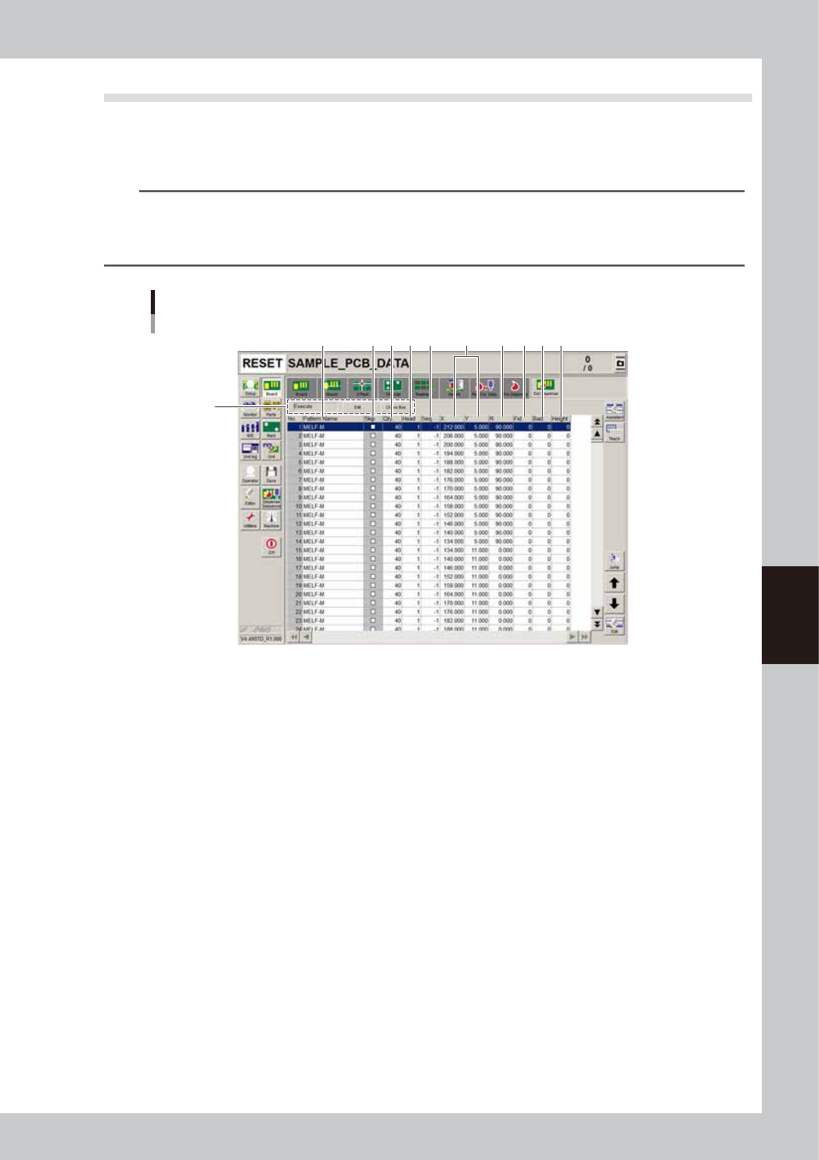
Dot dispense parameter screen
2
1
3 7 94 5 6 108 11
64516-N7-00
1. Dot dispense parameters
Set whether to perform dot dispense.
To change the current setting, press the [Edit] button. If skip is selected, dot dispense will be skipped.
2. Pattern Name
Enter the desired dot dispense name.
3. Skip
Set whether to perform dot dispense for each component.
4. Qty
Set the quantity of dot dispensing liquid.
5. Head
Set the head No. to be used for dot dispense.
6. Sequence
Specify the desired dispense operation sequence number for which dot dispense quantity, head up/ down speeds, etc.
have been set beforehand.
If "-1" is entered, an optimal dispense operation sequence will be selected automatically according to the nozzle type
and adhesive quantity.
7. X, Y
Set the dot dispense XY coordinates so that dots are not overlapped.
8. R
Set the dispense angle. "+" indicates counter-clockwise, and "-" indicates clockwise.

5-34
5
Creating the board data
9. Fid.
Set the fiducial No. to be used for dot dispense.
If you are not using the fiducial function, set "0".
10. Bad
Set the badmark No. to be used for dot dispense.
If you are not using badmarks, set "0".
11. Height Correction
This parameter appears only when the machine is equipped with an optional laser displacement meter.
Enter the data No. that was set on the [Height Correction] tab.
Enter “0” if not using the height correction function.
5-35
5
Creating the board data
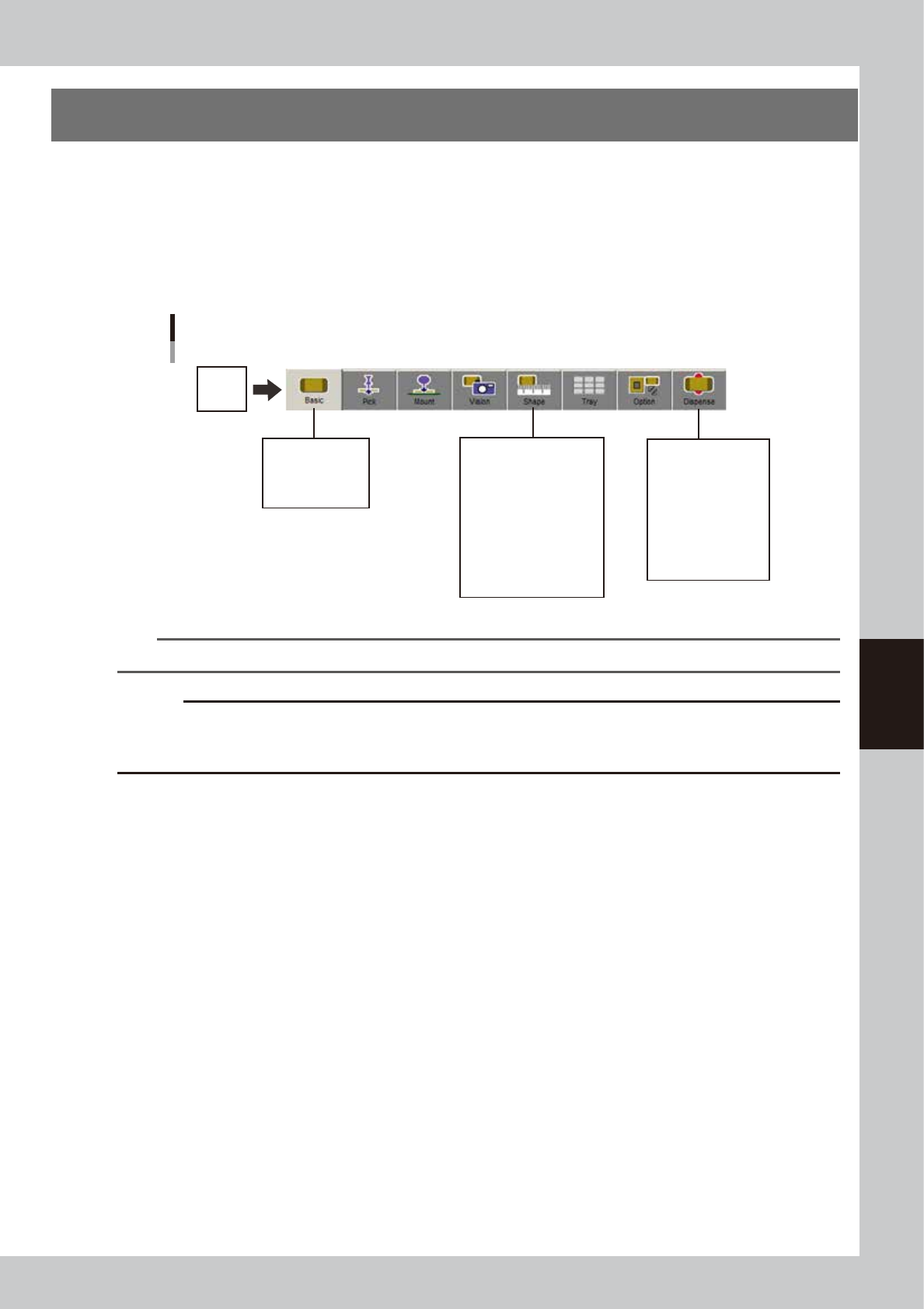
5. Creating the component information
This section explains how to create data of components to be mounted on the board. Component information
consists of various parameters as shown below for each registered component name. These parameters can
be set easily by copying the sample data of a similarly shaped component from the database and changing
the parameters that differ from that component.
Among these parameters, "Basic", "Shape" and "Dispense" parameters need to be set in the case of the
dispenser.
In this section, the setting method for each parameter is given for some commonly used components.
Parts
Component information parameters
Alignment Group
Alignment Type
Database Number
Required Nozzle
Dispense Nozzle
Dispens Unit
Ref. XY
Dot Extent XY
Dot Amount XY
Angle Offset
(Alignment Group)
(Alignment Type)
Body Size XY
Ruler Offset
Ruler Width
Lead Number
Lead Width
ReflectLL
Set these parameters
for solder type.
64517-N7-00
TIP
Parameters displayed somewhat differ depending on the selected component type and package style.
c
CAUTION
Set the Shape parameters when creating data for solder type. The following Alignment Type items are not supported:
“Simple BGA”, “BGA”, “Simple flip chip”, Flip chip, “Mark, “Special rectangle”, “Center-of-gravity detection”, “No
recognition”, “Special data”, “Nozzle check” and “No setting”.