YSD_Users_E.pdf - 第226页
5-37 5 Creating the board data 5.2 Chip components T his section explains how to set the parameters for chip components. 5.2.1 Basic parameters Set basic parameters for c hip components. On dispenser machines, c heck/edi…
5-36
5
Creating the board data
5.1 Creating procedure
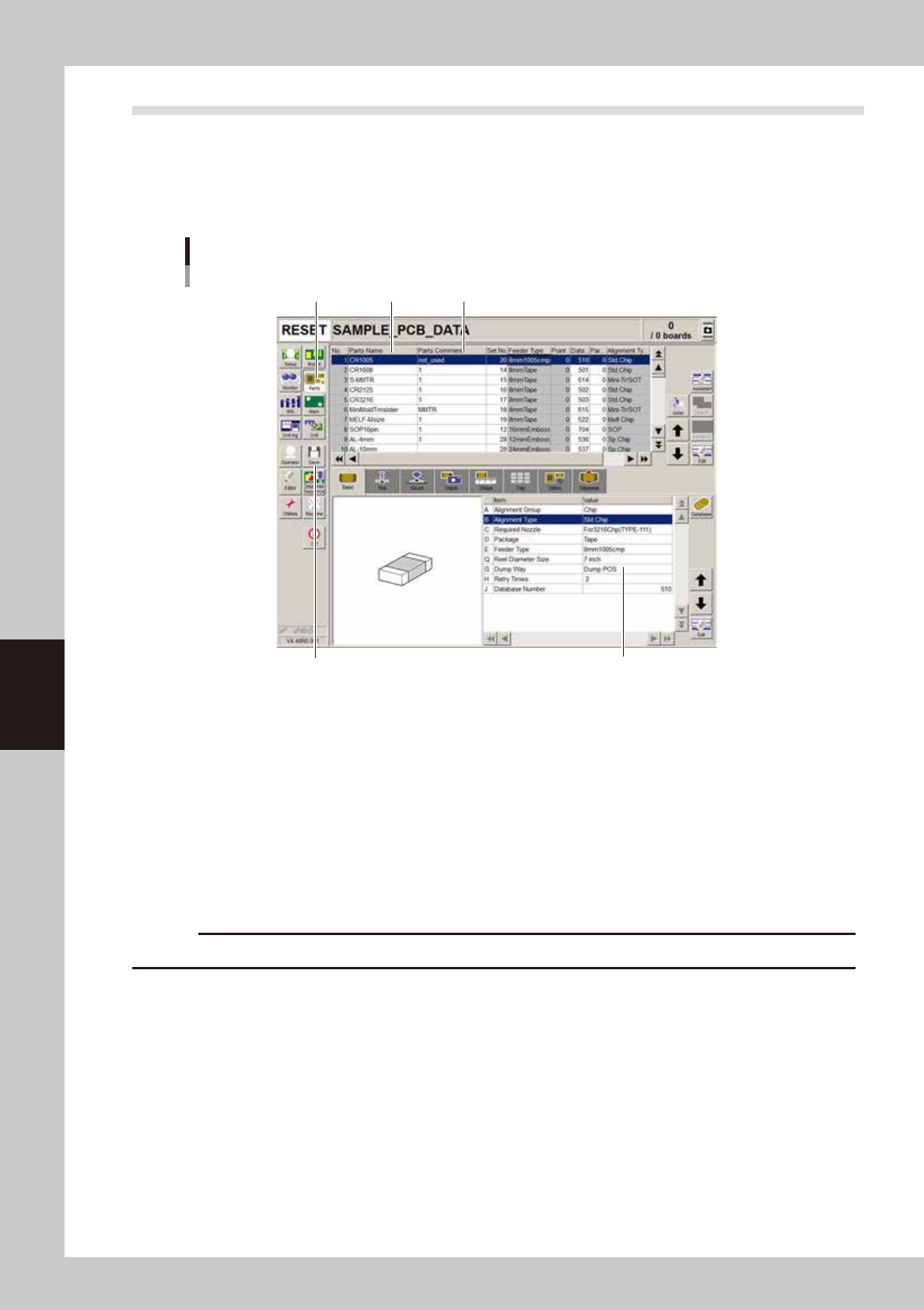
After selecting the board name, press the [Parts] button in the main menu button area to open the component
information screen. Enter the component name and comment in the upper grid of the screen, and set the
parameters in the right lower grid as explained below.
1
Press the [Parts] button to open the component information screen.
Component information screen
Step 1 Step 2 Step 3
Step 4
Step 6
64518-N7-00
2
Enter the component name in the Part Name column.
Enter the name printed on the tape reel or on the component itself within 19 alphanumeric characters.
A space cannot be included in the name.
3
Enter a comment.
Type any desired comment in the Parts Comment column as necessary. You can omit entering
comments here.
4
Set the parameters.
While selecting the [Basic], [Shape], [Dispense] tabs and so forth, set the necessary parameters in the
lower right grid. (Refer to sections "4.2" to "4.5" for details.)
c
CAUTION
Set the Shape parameters when creating data for solder type.
5
Repeat the above steps for other components.
Repeat the same procedure from step 2 to register all components to be mounted on the board.
6
Save the data.
Press the [Save] button to store the data.
5-37
5
Creating the board data
5.2 Chip components
This section explains how to set the parameters for chip components.
5.2.1 Basic parameters
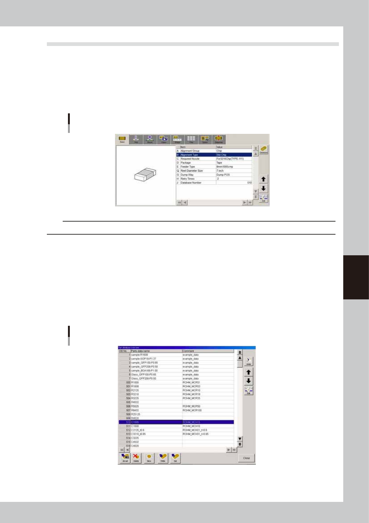
Set basic parameters for chip components.
On dispenser machines, check/edit the settings for the parameters "A: Alignment Group", "B: Alignment Type"
and "J: Database Number".
The other parameters are not used for dispenser machines.
Basic parameters
64519-N7-00
TIP
The “Alignment Group” and “Alignment Type” parameters are also displayed on the [Shape] tab screen.
A: Alignment Group
Set to "Chip".
B: Alignment Type
Set this parameter when creating data for solder type. Specify the type of chip component. For example, set standard box
type chip components to "Std. Chip", and Melf components to "Melf Chip".
J: Database number
Shows the database number when the parameter values were copied from the database.
When you want to copy the parameter values from the database, press the [Database] button to open the database list.
Then select the copy source data and press the [Set] button to make a copy.
Database list
64520-N7-00
5-38
5
Creating the board data
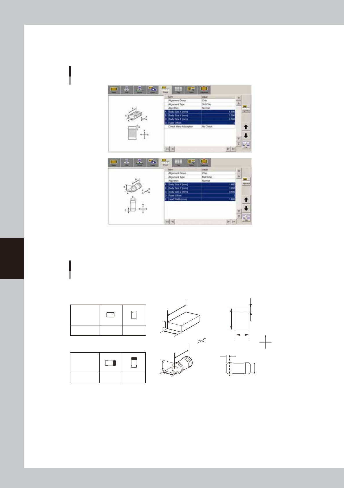
5.2.2 Shape parameters
Set these parameters after specifying “Alignment Type”. If “Alignment Type” is undefined, the following
parameters are not displayed.
Shape parameters
64522-N7-00
A, B: Body Size X, Body Size Y
Enter the correct dimensions (mm) measured with a vernier caliper or micrometer.
Parts orientation and shape parameters
0° 90°
Loading
position
Pickup angle
NS
E
W
N
S
WE
0° 90°
Loading
position
Pickup angle
NS
E
W
N
S
WE
N
S
E
W
A
C
B
N
S
WE
A
B
D
Top view
C
A
B
E
D
A : Body Size X
B : Body Size Y
C : Body Size Z
D : Ruler Offset
E : Lead Width
Square chip
Melf chip
63516-N7-00
C: Body Size Z (Not used with this machine.)
D: Ruler Offset (Not used with this machine.)
E: Lead Width (Not used with this machine.)
Check Many Adsorption (Not used with this machine.)