YSD_Users_E.pdf - 第229页
5-40 5 Creating the board data 5.3 IC components 5.3.1 Mini-mold transistors and SOT P arameter examples for mini-mold transistors and SO T are given below . F or parameters not explained here, refer to the description i…
5-39
5
Creating the board data
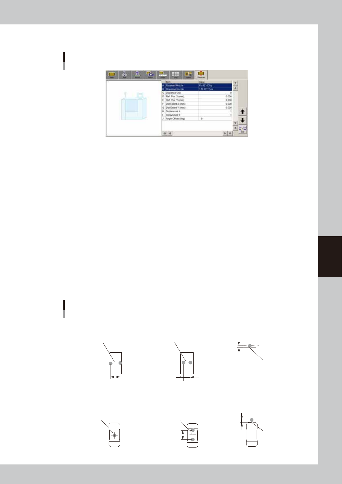
5.2.3 Dispense parameters
Dispense parameters
64523-N7-00
A: Required Nozzle
Select the nozzle to be used for dispense.
B: Dispense Nozzle
Select the nozzle type from "1 SHOT Type" or "2 SHOT Type".
C: Dispense Unit
Set the quantity of adhesive to be dispensed.
D, E: Ref. Pos. X (mm), Ref. Pos Y (mm)
In the case of bond type adhesive, set the deviation between the center of dispense and that of the component.
In the case of solder type adhesive, set the offset from the outer line of the component.
F, G: Dot Extent X (mm), Dot Extent Y (mm)
Set the dispense area (dot extend).
This parameter will be ignored if solder type adhesive is used.
H, I: Dot Amount X, Dot Amount Y
Set the number of dots to be dispensed in X and Y directions within the specified dispense area (Dot Extent).
This parameter will be ignored if solder type adhesive is used.
J: Angle Offset
Set the dispense angle. An angle between 0 and ±90° can be set in 5° steps.
Dispense for chip components
Center of component
Reference position
■ 1-shot nozzle (bond) ■ 2-shot nozzle (bond) ■ 1-shot nozzle (solder)
X-directional dot extent
Center of component
Varies with 2-shot nozzle pitch.
Reference
position Y
Dispense for square chip components
Center of component
■ 1-shot nozzle (bond)
■ 2-shot nozzle (bond)
(Dispense angle offset: 90°)
Center of component
Varies with
2-shot nozzle pitch.
■ 1-shot nozzle (solder)
Reference position
(0.00)
Reference
position Y
Dispense for Melf components
63519-N7-00
5-40
5
Creating the board data
5.3 IC components
5.3.1 Mini-mold transistors and SOT
Parameter examples for mini-mold transistors and SOT are given below. For parameters not explained here,
refer to the description in "5.2 Chip Components" of this chapter.
Mini-mold transistor parameters
Basic Shape Dispense
64524-N7-00
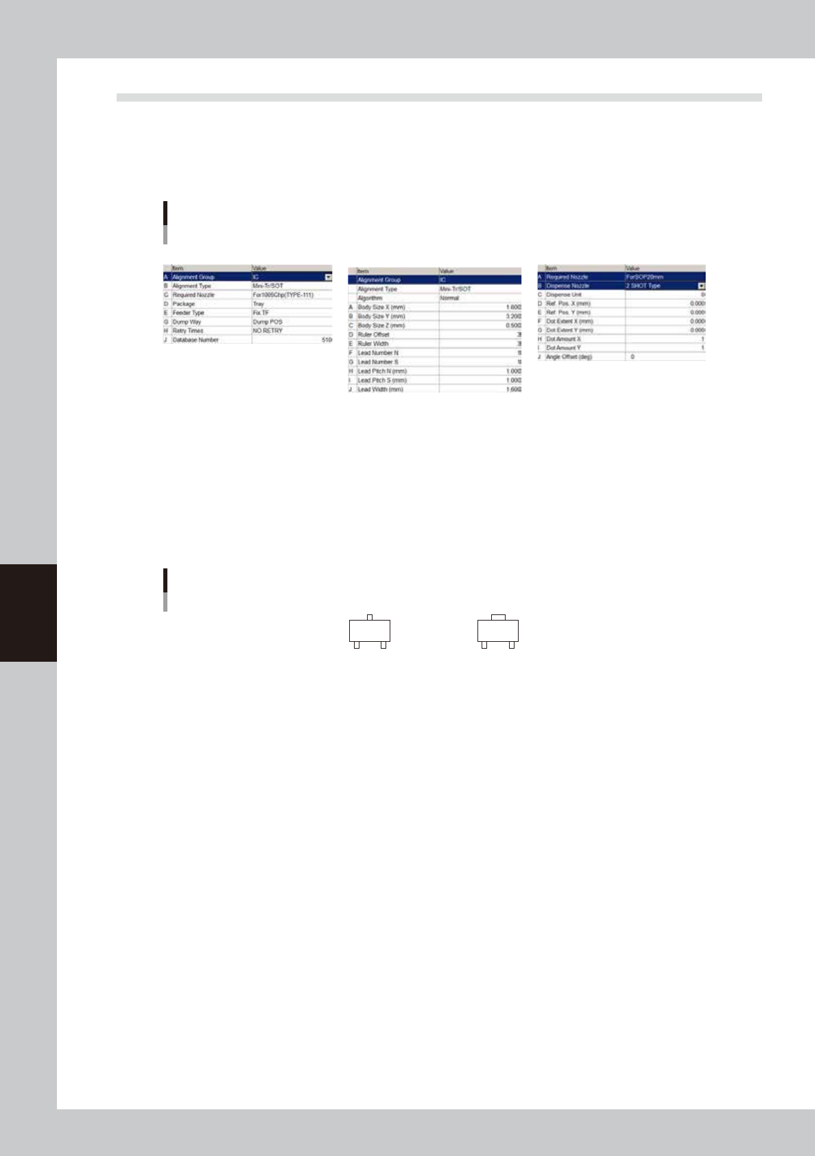
Basic parameters
A: Alignment Group
Set this parameter to “IC”.
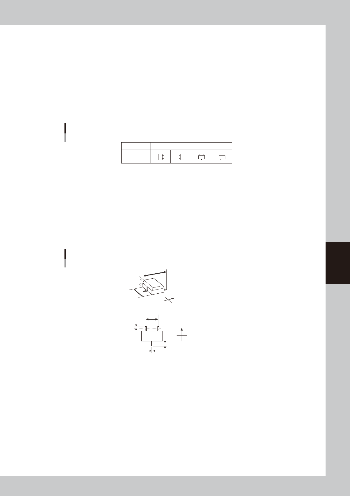
B: Alignment Type
Set this parameter when creating data for solder type. Set to “Mini Tr/SOT” when the shapes of the opposing leads are
identical, and set to “P-Tr” when not identical.
Alignment Type setting for transistors
Mini Tr/SOT
P-Tr
63520-N7-00
5-41
5
Creating the board data
Shape parameters
Set these parameters after specifying “Alignment Type”. If “Alignment Type” is undefined, the following parameters are
not displayed.
A, B: Body Size X, Body Size Y
Enter the correct dimensions (mm) including the leads, measured with a vernier caliper or micrometer.
D: Ruler Offset (Not used with this machine.)
E: Ruler Width (Not used with this machine.)
F, G: Lead Number NS
Enter the number of leads existing in the N and S directions.
Lead NS directions
Pickup angle
Loading
position
0° 90°
NS NS
N
S
N
S
63522-N7-00
H, I: Lead Pitch NS
Enter the correct lead pitch (lead-to-lead spacing).
J: Lead Width (Not used with this machine.)
Enter the correct lead width.
K: ReflectLL (Not used with this machine.)
Enter the projected length of leads which reflect light during recognition. Use the default setting in most
cases.
Shape parameters for mini-mold transistors
K
N
S
E
W
B
C
A
N
S
E
W
H
D
J
A : Body Size X
B : Body Size Y
C : Body Size Z
D : Ruler Offset
H : Lead Pitch
J : Lead Width
K : Reflect LL
Bottom view
63523-N7-00