YSD_Users_E.pdf - 第230页
5-41 5 Creating the board data Shape parameters Set these parameters after specifying “ Alignment T ype”. If “ Alignment T ype” is undefined, the following parameters are not display ed. A, B: Body Size X, Body Size Y En…
5-40
5
Creating the board data
5.3 IC components
5.3.1 Mini-mold transistors and SOT
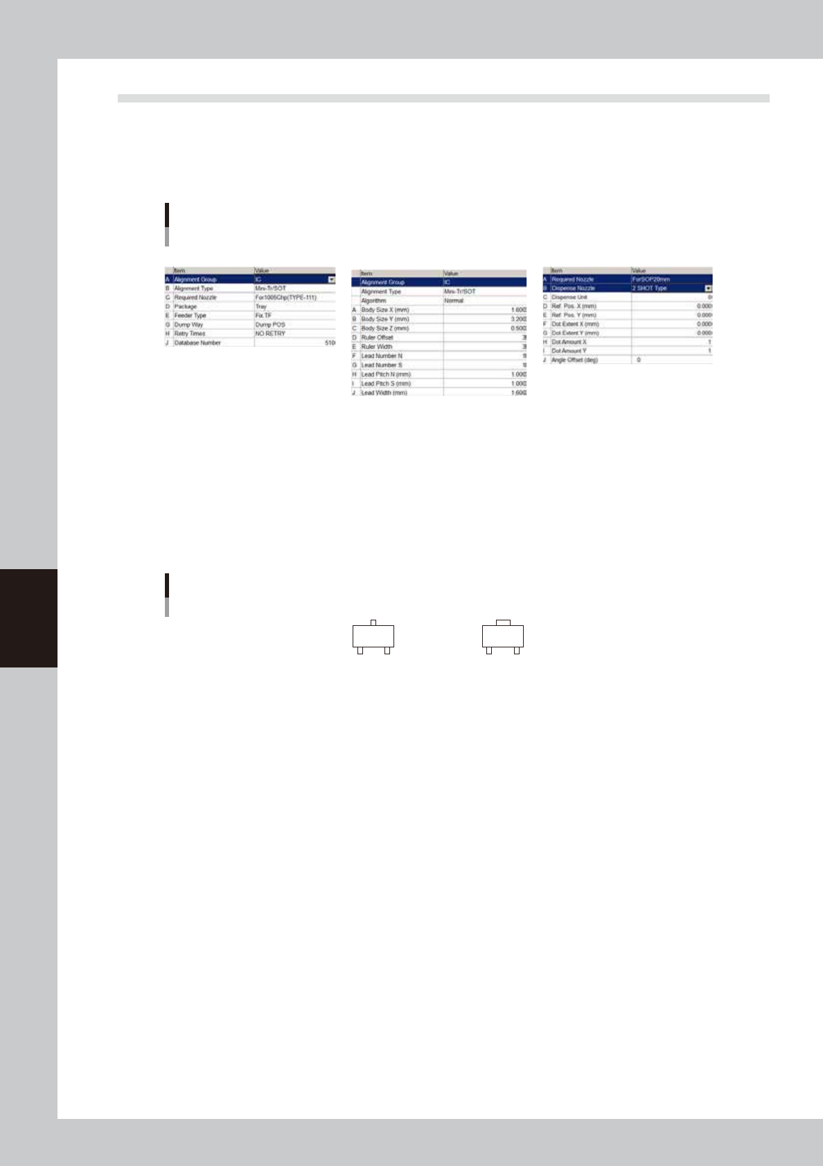
Parameter examples for mini-mold transistors and SOT are given below. For parameters not explained here,
refer to the description in "5.2 Chip Components" of this chapter.
Mini-mold transistor parameters
Basic Shape Dispense
64524-N7-00
Basic parameters
A: Alignment Group
Set this parameter to “IC”.
B: Alignment Type
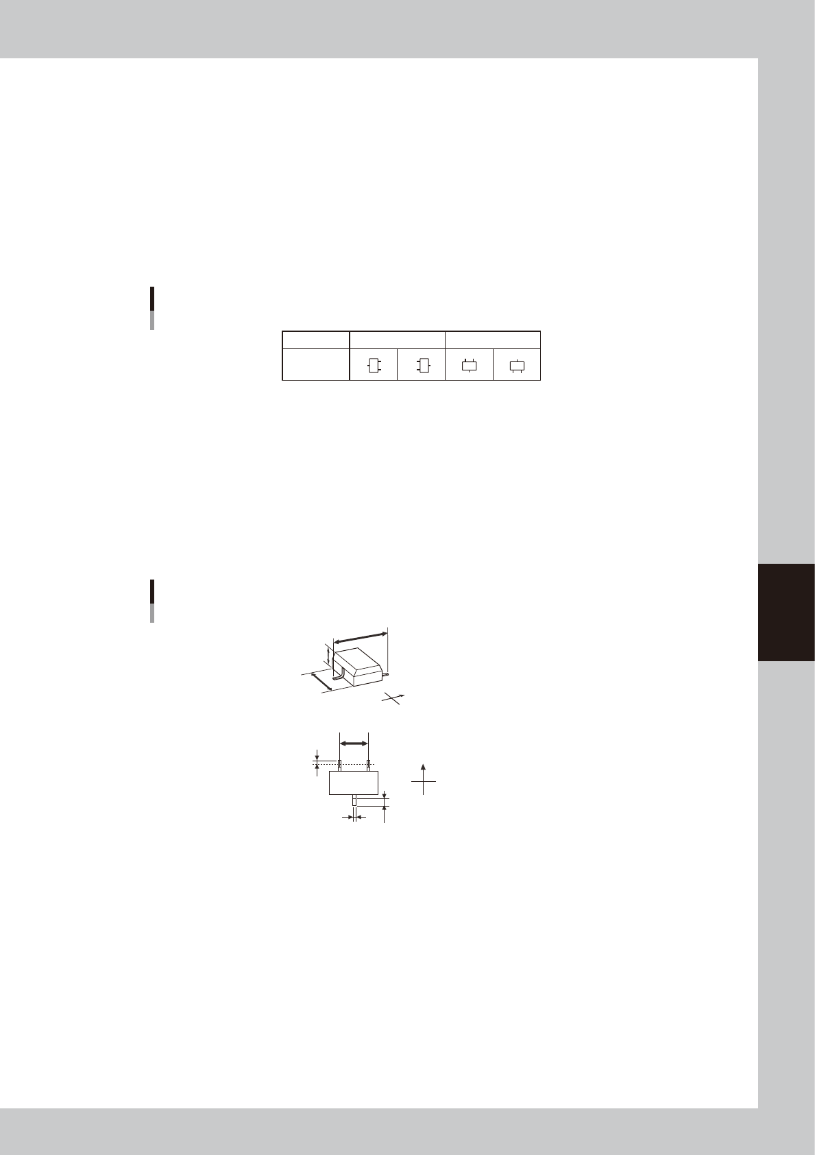
Set this parameter when creating data for solder type. Set to “Mini Tr/SOT” when the shapes of the opposing leads are
identical, and set to “P-Tr” when not identical.
Alignment Type setting for transistors
Mini Tr/SOT
P-Tr
63520-N7-00
5-41
5
Creating the board data
Shape parameters
Set these parameters after specifying “Alignment Type”. If “Alignment Type” is undefined, the following parameters are
not displayed.
A, B: Body Size X, Body Size Y
Enter the correct dimensions (mm) including the leads, measured with a vernier caliper or micrometer.
D: Ruler Offset (Not used with this machine.)
E: Ruler Width (Not used with this machine.)
F, G: Lead Number NS
Enter the number of leads existing in the N and S directions.
Lead NS directions
Pickup angle
Loading
position
0° 90°
NS NS
N
S
N
S
63522-N7-00
H, I: Lead Pitch NS
Enter the correct lead pitch (lead-to-lead spacing).
J: Lead Width (Not used with this machine.)
Enter the correct lead width.
K: ReflectLL (Not used with this machine.)
Enter the projected length of leads which reflect light during recognition. Use the default setting in most
cases.
Shape parameters for mini-mold transistors
K
N
S
E
W
B
C
A
N
S
E
W
H
D
J
A : Body Size X
B : Body Size Y
C : Body Size Z
D : Ruler Offset
H : Lead Pitch
J : Lead Width
K : Reflect LL
Bottom view
63523-N7-00
5-42
5
Creating the board data
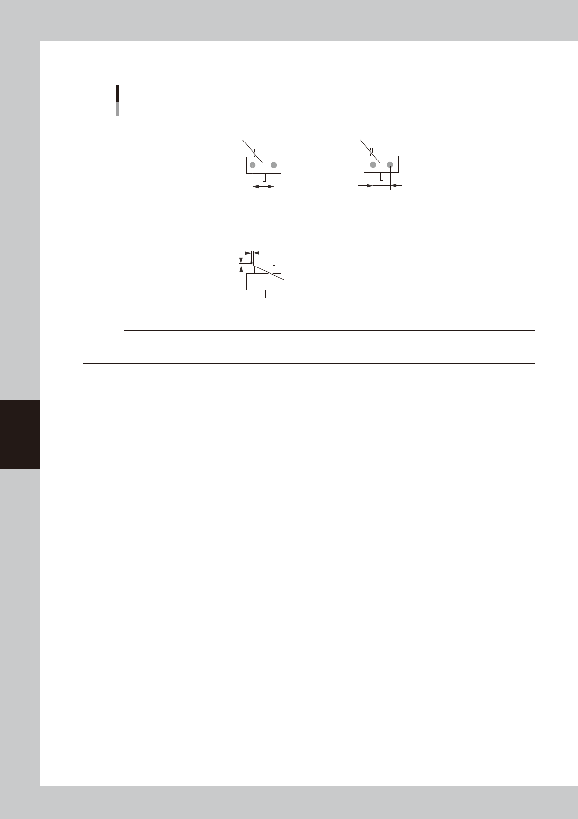
Dispense parameters
Dispense for mini-mold transistors
Center of component
■ 1-shot nozzle (bond)
X-directional dot extent
■ 2-shot nozzle (bond)
Center of component
Varies with 2-shot nozzle pitch.
Lead end
■ 1-shot nozzle (solder)
Reference
position Y
Reference position X
Reference position (0.00)
63524-N7-00
c
CAUTION
When using solder paste for mini-mold transistors, dispensing positions must be shifted to prevent solder paste
contacting adjacent leads.