YSD_Users_E.pdf - 第232页
5-43 5 Creating the board data 5.3.2 SOP components SOP components are registered with the parameters shown belo w . Refer to the description in "5.2 Chip components" for parameters not explained here. SOP comp…
5-42
5
Creating the board data
Dispense parameters
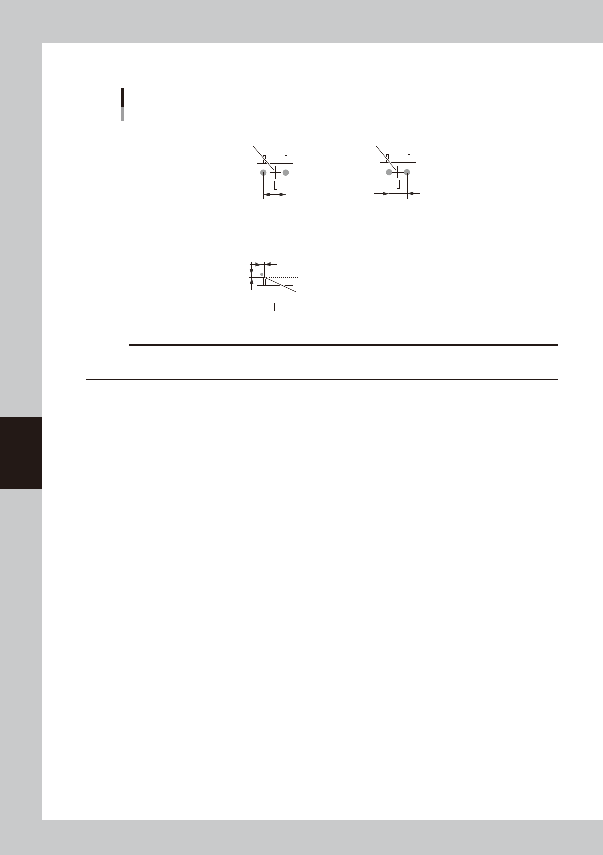
Dispense for mini-mold transistors
Center of component
■ 1-shot nozzle (bond)
X-directional dot extent
■ 2-shot nozzle (bond)
Center of component
Varies with 2-shot nozzle pitch.
Lead end
■ 1-shot nozzle (solder)
Reference
position Y
Reference position X
Reference position (0.00)
63524-N7-00
c
CAUTION
When using solder paste for mini-mold transistors, dispensing positions must be shifted to prevent solder paste
contacting adjacent leads.
5-43
5
Creating the board data
5.3.2 SOP components
SOP components are registered with the parameters shown below. Refer to the description in "5.2 Chip components" for
parameters not explained here.
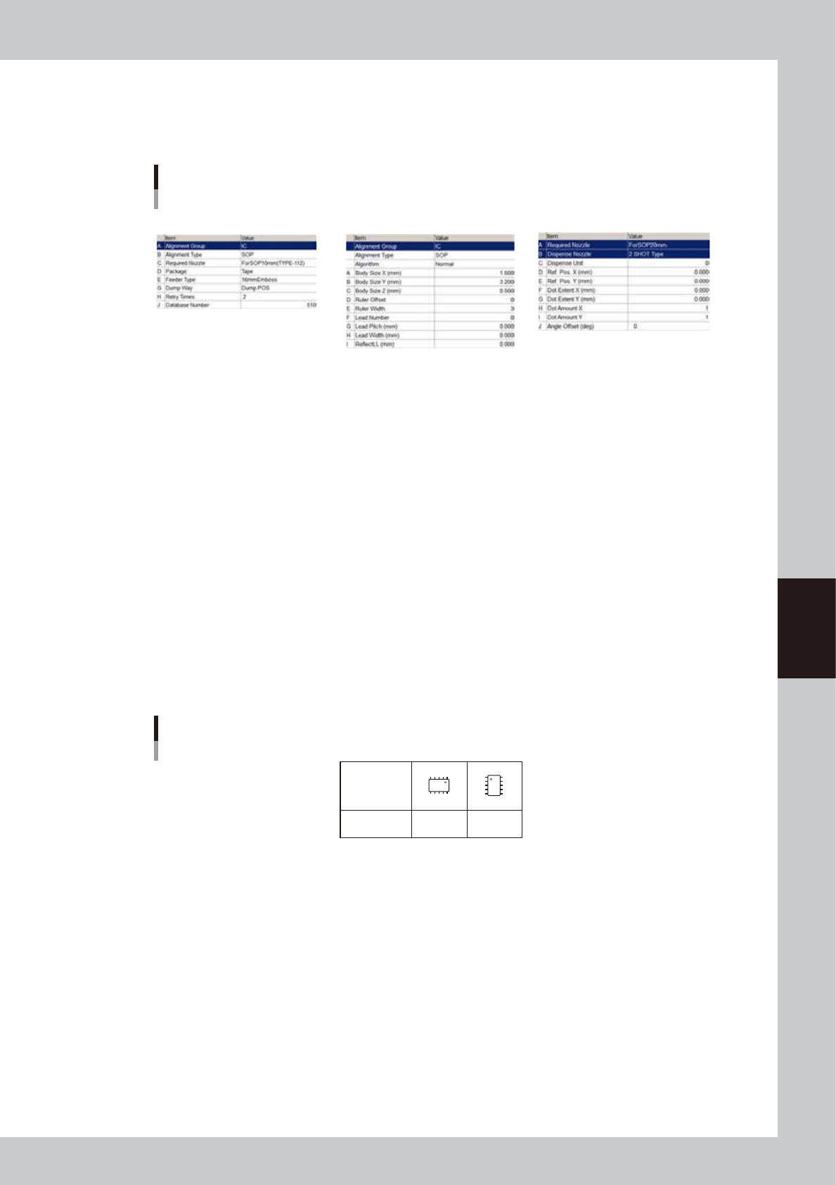
SOP component parameters
Basic Shape Dispense
64525-N7-00
Basic parameters
A: Alignment Group
Set this parameter to “IC”.
B: Alignment Type
Set to “SOP”.
Shape parameters
Set these parameters after specifying “Alignment Type”. If “Alignment Type” is undefined, the following parameters are
not displayed.
A, B: Body Size X, Body Size Y
Enter the correct dimensions (mm) including the leads, measured with a vernier caliper or micrometer.
D: Ruler Offset (Not used with this machine.)
E: Ruler Width (Not used with this machine.)
F: Lead Number
Enter the number of leads existing in the E or W direction.
SOP directions
0° 90°
Loading
position
Pickup angle
NS
E
W
N
S
WE
63525-N7-00
G: Lead Pitch
Enter the correct lead pitch (lead-to-lead spacing).
H: Lead Width (Not used with this machine.)
Enter the correct lead width
I: ReflectLL (Not used with this machine.)
Enter the projected length of leads which reflect light during recognition. Use the default setting in most cases.
5-44
5
Creating the board data
Shape parameters for SOP
A : Body Size X
B : Body Size Y
C : Body Size Z
G : Lead Pitch
H : Lead Width
I : Reflect LL
Bottom view
N
S
E
W
B
C
A
N
S
W
E
G
H
I
63527-N7-00
Dispense parameters
Dispense for SOP components
■ 2-shot nozzle (bond)
(3-point dispense)
Y-directional
dot extent
Center of component
Varies with 2-shot
nozzle pitch.
Lead end position
■ 1-shot nozzle (bond)
Reference position (0.00)
Reference position X
■ 1-shot nozzle (bond)
(3-point dispense)
Center of component
Y-directional
dot extent
63528-N7-00
c
CAUTION
• When using solder paste for SOP components, the amount of solder paste may be insufficient if dispense is
performed only twice for each lead.
• When using solder paste for SOP components, dispense may not be possible if the lead pitch is 0.8 mm or narrower.