YSD_Users_E.pdf - 第239页
5-50 5 Creating the board data Dispense parameter Dispense for connector components Center of component ■ 1-shot nozzle (bond) Y -directional dot extent ■ 2-shot nozzle (bond) Y -directional dot extent Center of componen…
5-49
5
Creating the board data
Shape parameters
Set these parameters after specifying “Alignment Type”. If “Alignment Type” is undefined, the following parameters are
not displayed.
A, B: Body Size X, Body Size Y
Enter the correct dimensions (mm) including the leads, measured with a vernier caliper or micrometer.
D to F: Contr. Offset XYR
Enter the values to correct the lead offset (positional shift) from the center of the component.
G: Ruler Offset
Enter the distance in pixels from the end of the leads to an imaginary line used to measure the lead width and pitch. Use
the default setting in most cases.
H: Ruler Width
Enter the width of an imaginary line used to measure the lead width and pitch. Set this parameter to "1 to 2" for
components with a lead length shorter than 0.3 mm, and to "2 to 3" for components with a lead length longer than 0.3
mm. Use the default setting in most cases.
I: LeadNumber
Enter the number of leads existing on one side.
N
N
N
N
S
S
S
S
W
W
W
W
E
E
E
E
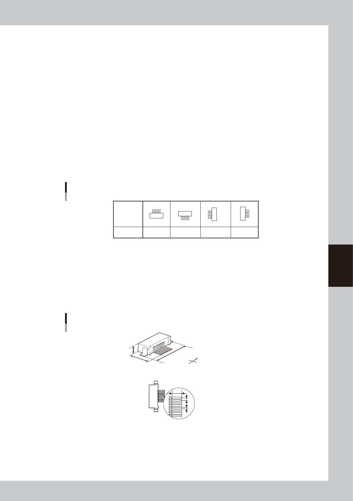
Connector orientation
Loading
position
Pickup angle
0° 180° 90° -90°
63534-N7-00
J: Lead Pitch
Enter the correct lead pitch (lead-to-lead spacing).
K: Lead Width
Enter the correct lead width.
L: ReflectLL
Enter the projected length of leads which reflect light during recognition. Use the default setting in most cases.
Shape parameters for connectors
A : Body Size X
B : Body Size Y
C : Body Size Z
J : Lead Pitch
K : Lead Width
L : Reflect LL
Bottom view
S
N
W
E
B
C
A
L
J
K
63535-N7-00
5-50
5
Creating the board data
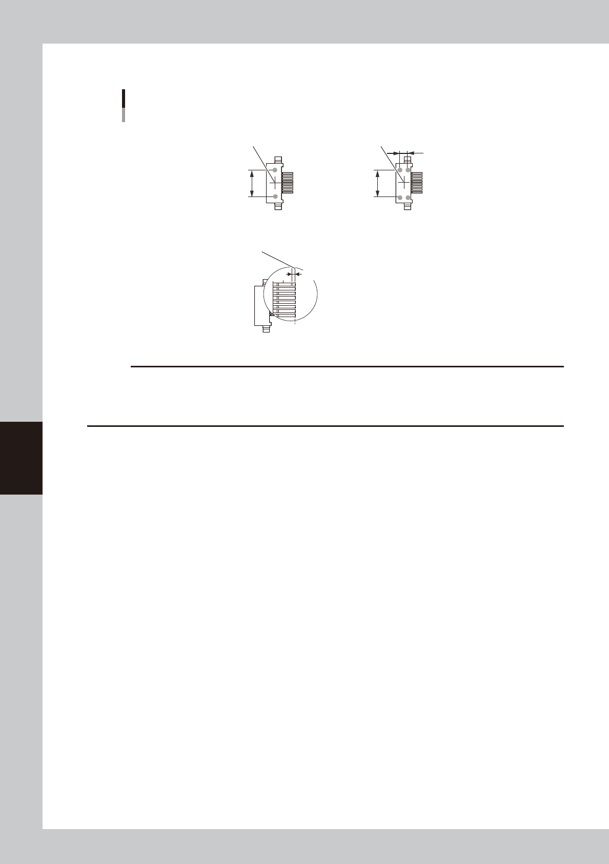
Dispense parameter
Dispense for connector components
Center of component
■ 1-shot nozzle (bond)
Y-directional
dot extent
■ 2-shot nozzle (bond)
Y-directional
dot extent
Center of component
Varies with
2-shot nozzle pitch.
Lead end position
■ 1-shot nozzle (solder)
Reference position (0.00)
Reference position X
63536-N7-00
c
CAUTION
• When using solder paste for connector components, the amount of solder paste may be insufficient if dispense is
performed only twice for each lead.
• When using solder paste for connector components, dispense may not be possible if the lead pitch is 0.8 mm or
narrower.
5-51
5
Creating the board data
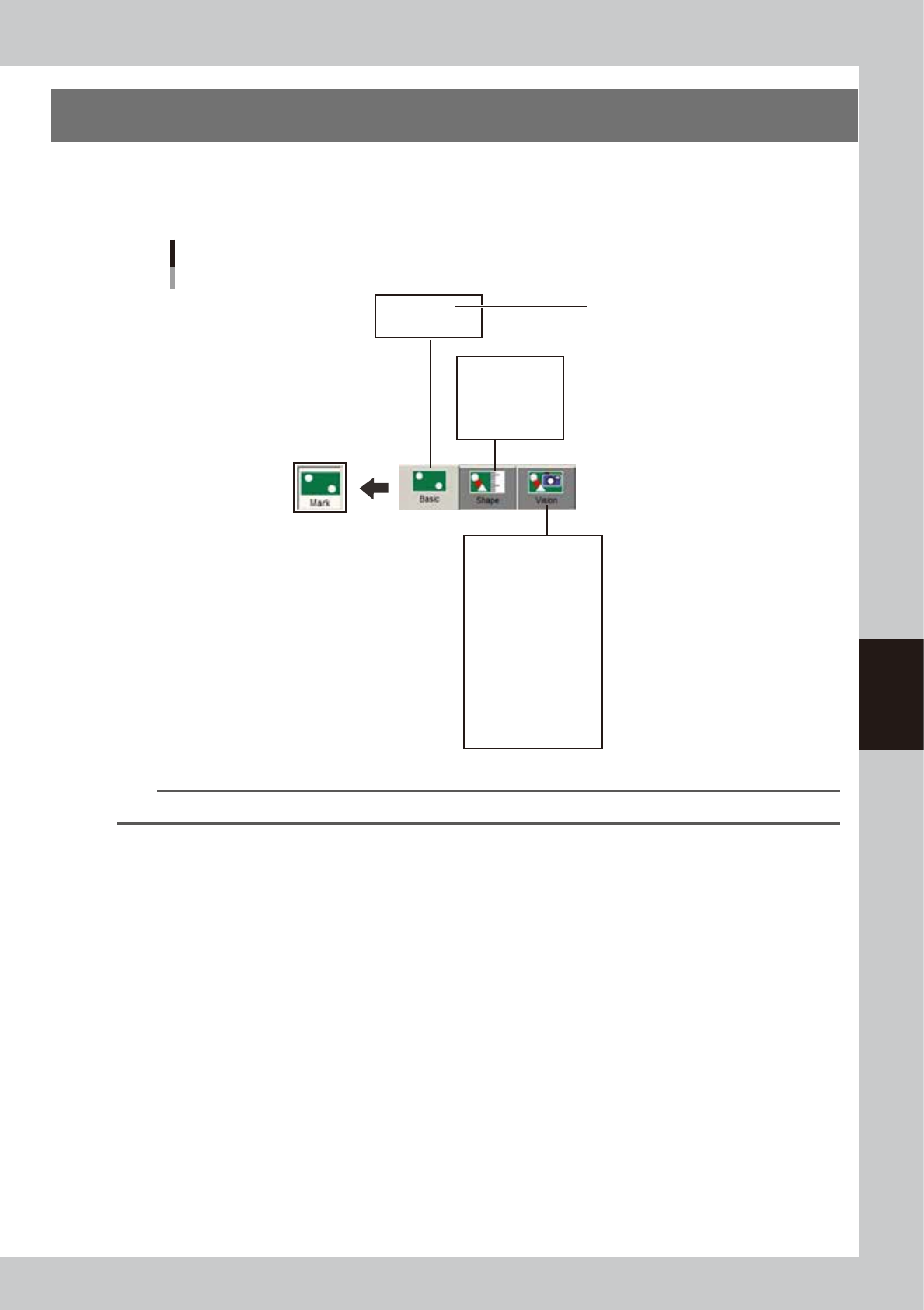
6. Creating the mark information
This section describes how to create mark information for fiducial marks used on a board. Mark information
has various parameters for each of the mark names registered. To set these parameters, copy sample data of
a mark with a similar shape from the database and edit only the different parameters.
Mark information parameters
Shape Type
Mark Out Size
(Mark Outline X)
(Mark Area)
(Mark Perimeter)
Mark Type
Database Number
Surface Type
Algorithm Type
Mark Threshold
Tolerance
Search Area XY
Outer Light
Inner Light
Coaxial Light
IR Outer Light
IR Inner Light
Cut Outer Noise
Cut inner Noise
Sequence
Mark Name
Mark Comment
(Mark Type)
• Fiducial
• Badmark
• Fid for Bad
• Dispense Dot
• Height Correction
64529-N7-00
TIP
The displayed parameters vary with the selected "Mark Type" and "Shape Type",