YSD_Users_E.pdf - 第240页
5-51 5 Creating the board data 6. Creating the mark infor mation This section describes how to create mark information for fiducial marks used on a board. Mark information has various parameters for each of the mark name…
5-50
5
Creating the board data
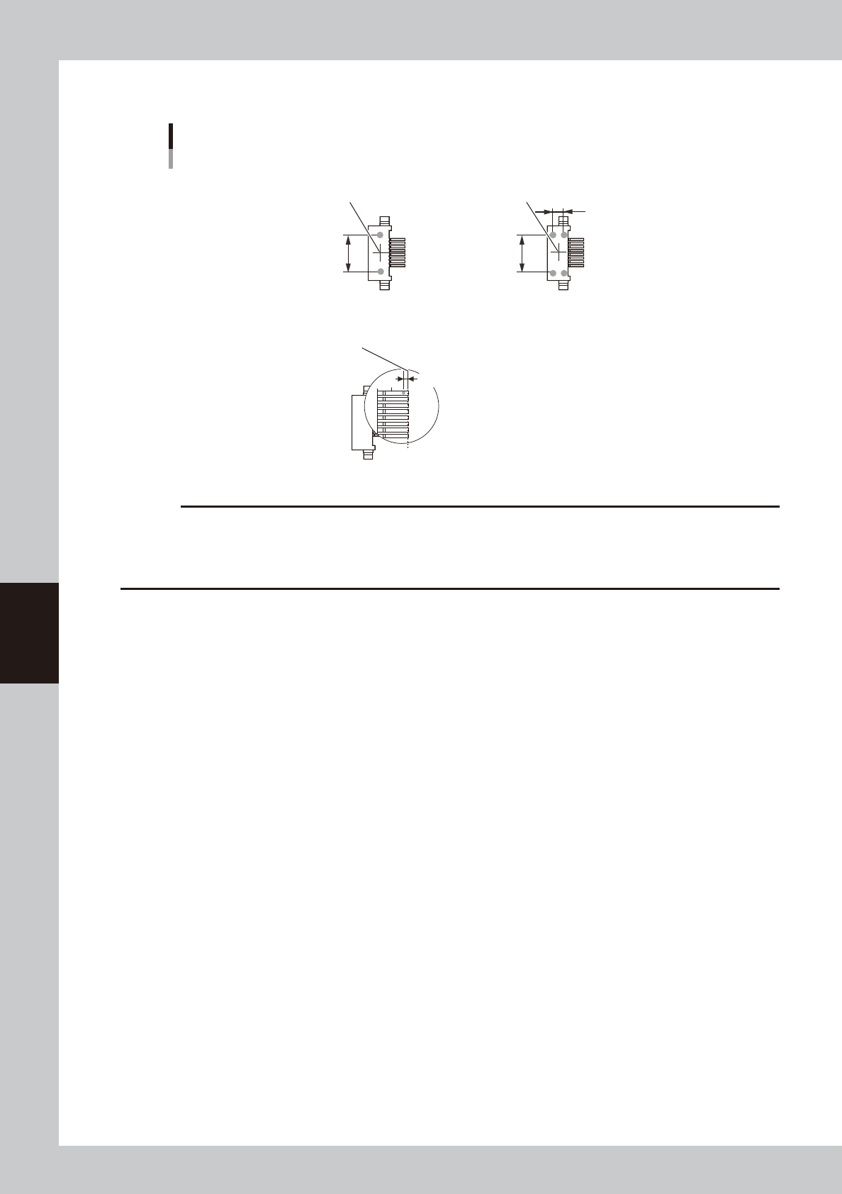
Dispense parameter
Dispense for connector components
Center of component
■ 1-shot nozzle (bond)
Y-directional
dot extent
■ 2-shot nozzle (bond)
Y-directional
dot extent
Center of component
Varies with
2-shot nozzle pitch.
Lead end position
■ 1-shot nozzle (solder)
Reference position (0.00)
Reference position X
63536-N7-00
c
CAUTION
• When using solder paste for connector components, the amount of solder paste may be insufficient if dispense is
performed only twice for each lead.
• When using solder paste for connector components, dispense may not be possible if the lead pitch is 0.8 mm or
narrower.
5-51
5
Creating the board data
6. Creating the mark information
This section describes how to create mark information for fiducial marks used on a board. Mark information
has various parameters for each of the mark names registered. To set these parameters, copy sample data of
a mark with a similar shape from the database and edit only the different parameters.
Mark information parameters
Shape Type
Mark Out Size
(Mark Outline X)
(Mark Area)
(Mark Perimeter)
Mark Type
Database Number
Surface Type
Algorithm Type
Mark Threshold
Tolerance
Search Area XY
Outer Light
Inner Light
Coaxial Light
IR Outer Light
IR Inner Light
Cut Outer Noise
Cut inner Noise
Sequence
Mark Name
Mark Comment
(Mark Type)
• Fiducial
• Badmark
• Fid for Bad
• Dispense Dot
• Height Correction
64529-N7-00
TIP
The displayed parameters vary with the selected "Mark Type" and "Shape Type",
5-52
5
Creating the board data
6.1 Creating procedure
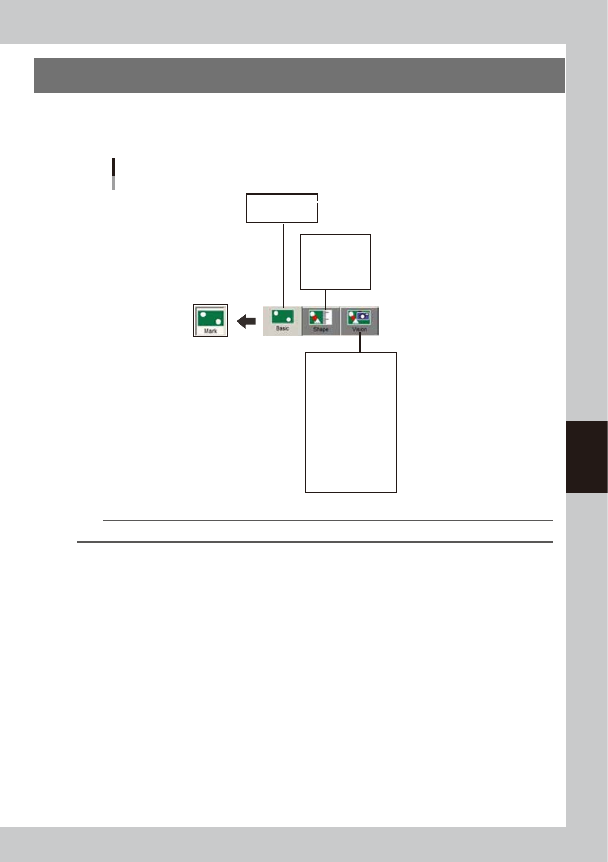
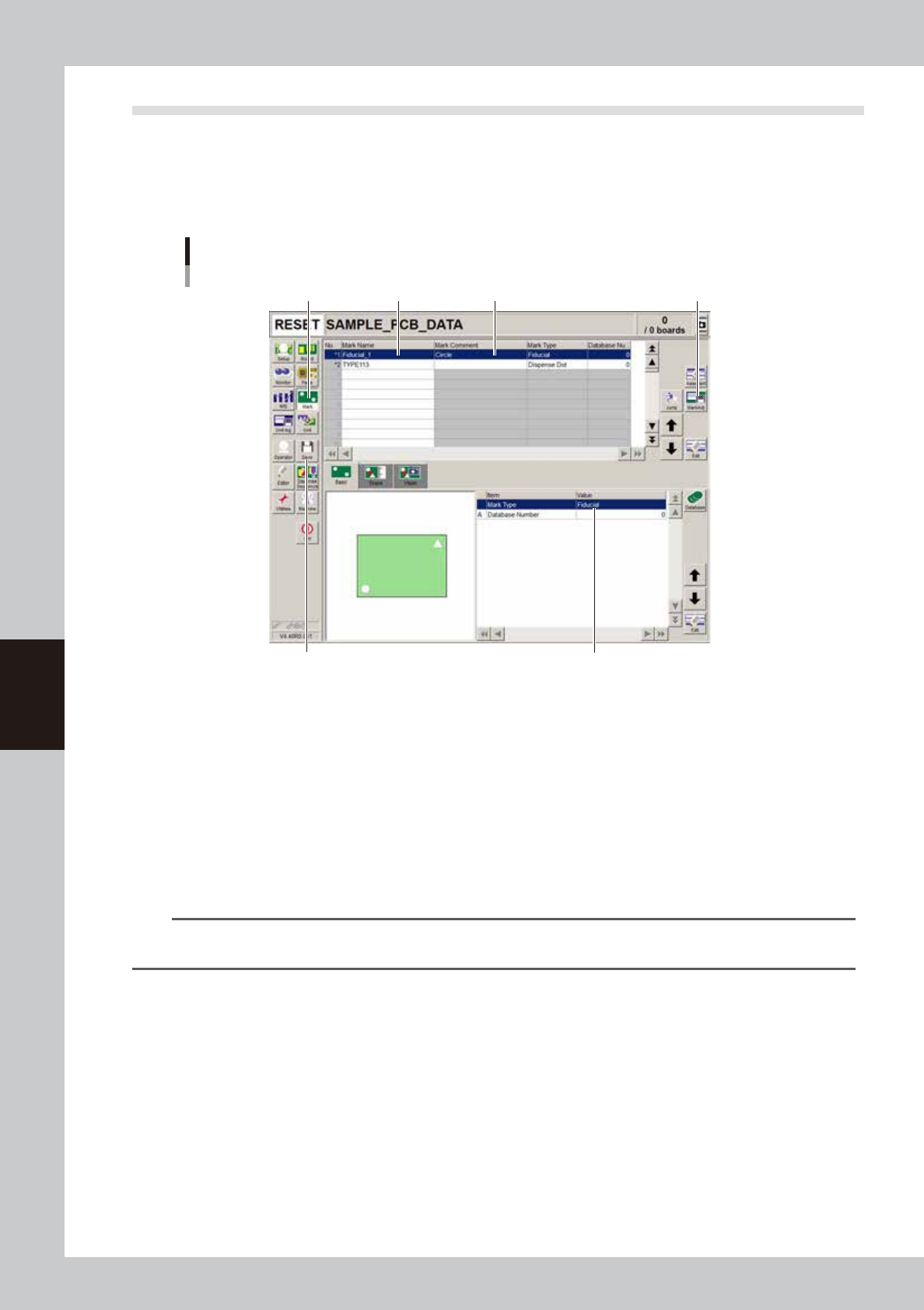
Pressing the Mark button in the menu button area opens the mark information screen as shown below. Enter
the mark name and comment in the upper grid of the screen, and set the parameters in the right lower grid as
explained below.
1
Press the [Mark] button to open the mark information screen.
Mark screen
Step 2Step 1 Step 3
Step 5
Step 4Step 7
64530-N7-00
2
Enter the mark name in the Mark Name column.
Enter a different name for each mark within 19 alphanumeric characters. A space cannot be included
in the name.
3
Enter a comment.
Type any desired comment in the Mark Comment column as necessary. You can omit entering
comments here.
4
Set the parameters.
While selecting the [Basic], [Shape], [Vision] tabs and so forth, set the necessary parameters in the right
lower grid. (See "6.2" to "6.4" in this section.)
TIP
When setting the mark parameters, it is handy to copy sample data of a mark with a similar shape from the database
and edit only the different parameters.
5
Adjust the parameters in the Parts Adjust mode.
Press the [Adjust] button to open the Parts Adjust window that allows you to adjust or check the
parameters of the selected component. (For more details, see “6.5 Mark Adjust mode” in this chapter.)
6
Repeat the above steps for other marks.
Repeat the same procedure from step 2 to register all marks to be used.
7
Save the data.
Press the [Save] button to store the data.