YSD_Users_E.pdf - 第247页
5-58 5 Creating the board data 6.5 Mark Adjust mode T his operation checks w hether the parameter settings are correct. F or parameters w hich are unspecified, the optimal values can be obtained b y performing “VISION TE…
5-57
5
Creating the board data
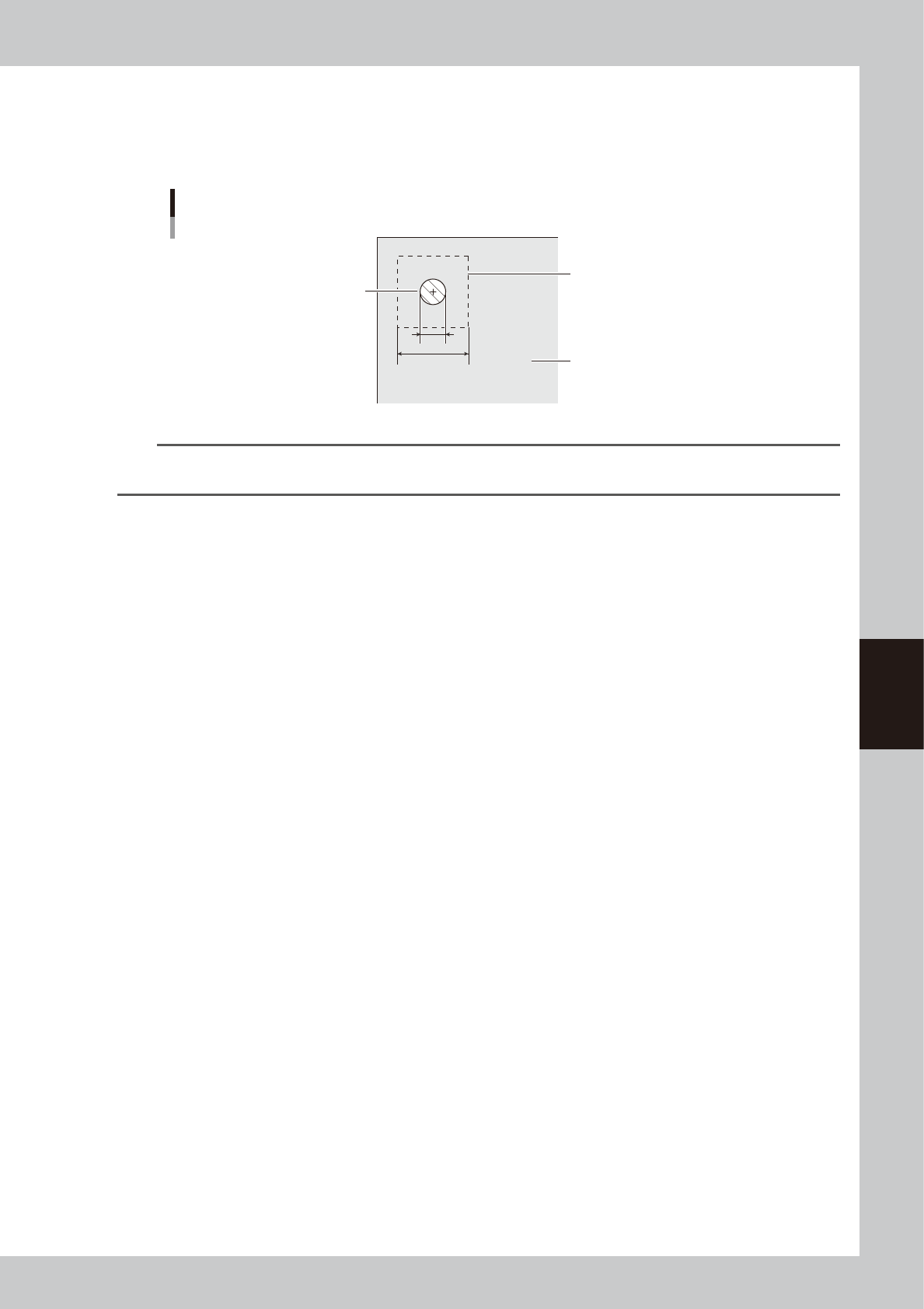
E, F: Search Area XY
As a general guide, set this parameter to the mark diameter plus 3mm. For example, when the mark diameter is 1 mm, set
this parameter to “4mm” as shown below. If other marks (such as resist, silk print, other patterns) exist in this search area,
make the Search Area setting smaller.
1
4
Search Area
Mark
Board
Search Area
63542-N7-00
TIP
The Search Area parameter is not displayed on the Vision tab screen when "Mark Type" of the Basic parameters is set
to "Badmark".
G to K: Light level
Lighting for recognizing a mark is divided into several zones. Light level in each zone is displayed here. Optimum light
levels can be found in the Mark Adjust mode explained later.
L, M: Cut Outer Noise, Cut Inner Noise
Values used to eliminate the areas that appear as a noise outside or inside the mark when the mark image is digitized.
Obtain the optimum values using the Mark Adjust mode that is explained in the next section, and enter the obtained
values.
N: Sequence
Set to "Normal" in most cases. If the recognition speed is important select "Quick", or if recognition accuracy is important
select "Fine".
5-58
5
Creating the board data
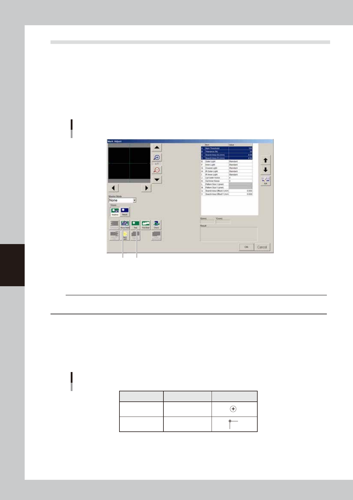
6.5 Mark Adjust mode
This operation checks whether the parameter settings are correct. For parameters which are unspecified, the
optimal values can be obtained by performing “VISION TEST” here. The following adjustment procedure is
explained for cases where “Mark Type” of the Basic parameters is set to “Fiducial”.
1
Select the mark data.
Open the mark information screen and line up the cursor with the mark data you want to check.
2
Press the [Mark Adj] button to enter the Mark Adjust mode.
The Mark Adjust window appears as shown below.
Mark Adjust window
Step 4 Step 5
64535-N7-00
3
Set the board on the conveyor and clamp it.
n
NOTE
Before clamping the board on the conveyor, you must adjust each conveyor unit. For the conveyor unit adjustment,
see "3.3 Changing the conveyor unit setup" in Chapter 2.
4
Perform teaching for the mark.
1. Press the [Move Head] button to open the Move Head window.
2. Use the arrow buttons to position the moving camera above the mark so the mark is aligned with the
cross cursor on the vision monitor as shown in the table below.
3. Press the [Close] button to return to the Mark Adjust window.
Shape Type Teaching point Example
Circle, Square
Triangle, Sp. Shape
Corner
Center of mark
Corner of mark
Mark teaching positions
63543-N7-00
5-59
5
Creating the board data
5
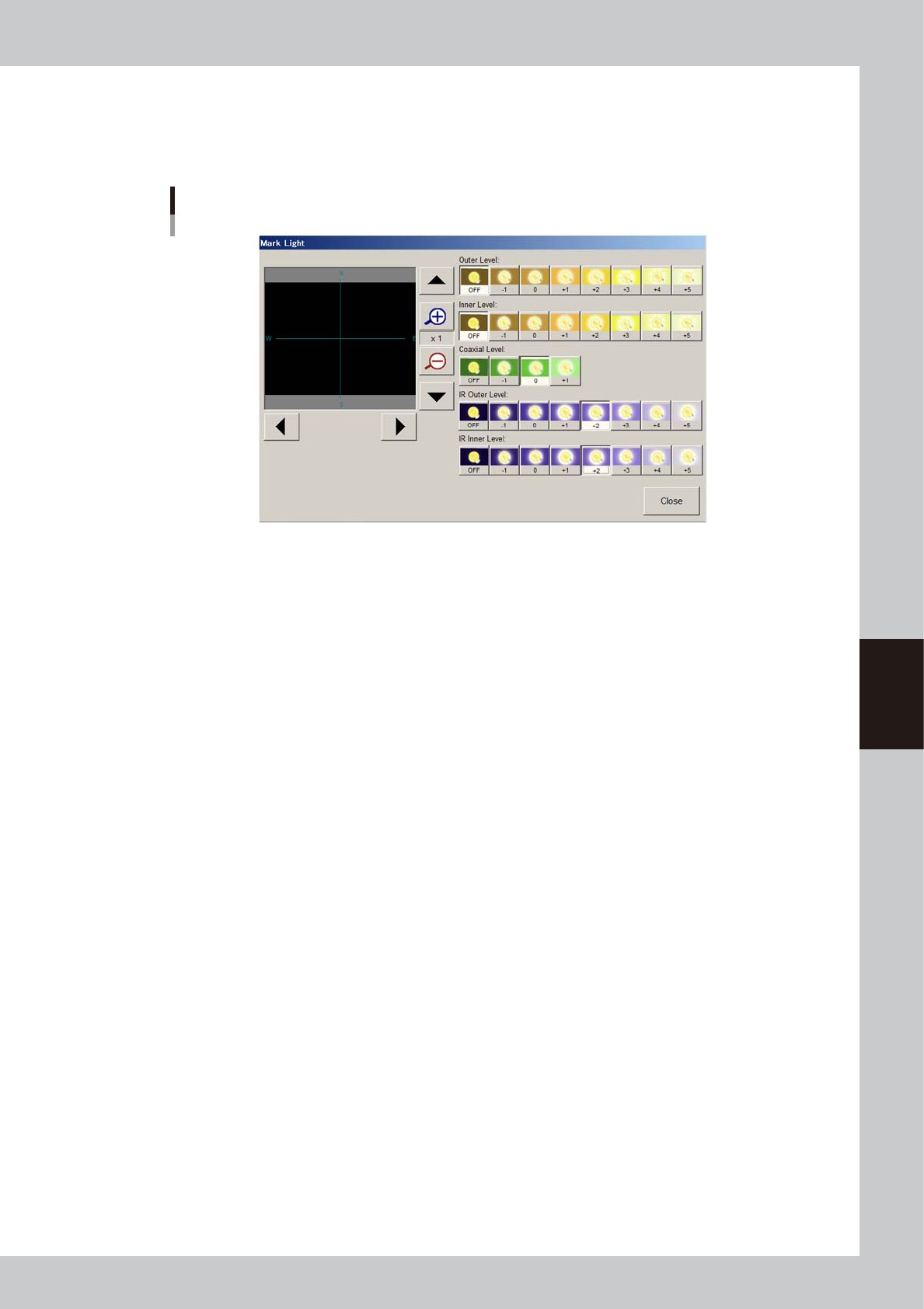
Adjust the light levels for the mark.
Press the [Mark Light] button to open the light level adjustment screen. Adjust the light level in each
lighting zone so that the entire mark is clearly and uniformly seen with a high contrast to the
background.
Mark lighting adjustment
64586-N7-00
As a general guide for adjusting mark lighting, try these suggestions.
• Copper foil, gold plating
Light up the "Outer Level", "Inner Level" and "Coaxial Level" (at "+1" light level).
If the mark is dark, then try increasing the "Inner Level".
• Solder leveler
Light up the "Outer Level", "Inner Level" and "Coaxial Level" (at "+1" light level).
If the mark surface is uneven and the mark contours appear faint and hard to see on the screen,
then try increasing the Outer Level.
• Metal mark on ceramic board
Light up the "Inner Level" and "Coaxial Level" (at "+1" light level).
If the ceramic portion is too bright, try lighting up the "IR Outer Level" and/or IR Inner Level" only.