YSD_Users_E.pdf - 第249页
5-60 5 Creating the board data 6 Pr ess the [ T est] button to per form the vision test. Repeat this test several times. If no error is detected, each parameter is appr opriate so advance to the next step. If an error oc…
5-59
5
Creating the board data
5
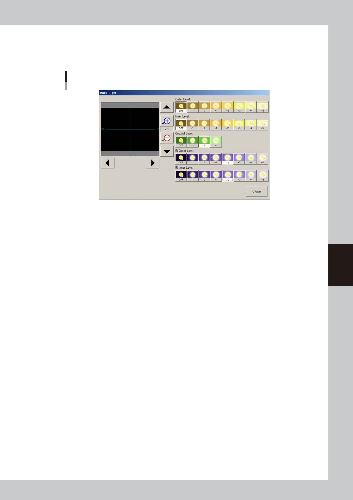
Adjust the light levels for the mark.
Press the [Mark Light] button to open the light level adjustment screen. Adjust the light level in each
lighting zone so that the entire mark is clearly and uniformly seen with a high contrast to the
background.
Mark lighting adjustment
64586-N7-00
As a general guide for adjusting mark lighting, try these suggestions.
• Copper foil, gold plating
Light up the "Outer Level", "Inner Level" and "Coaxial Level" (at "+1" light level).
If the mark is dark, then try increasing the "Inner Level".
• Solder leveler
Light up the "Outer Level", "Inner Level" and "Coaxial Level" (at "+1" light level).
If the mark surface is uneven and the mark contours appear faint and hard to see on the screen,
then try increasing the Outer Level.
• Metal mark on ceramic board
Light up the "Inner Level" and "Coaxial Level" (at "+1" light level).
If the ceramic portion is too bright, try lighting up the "IR Outer Level" and/or IR Inner Level" only.
5-60
5
Creating the board data
6
Press the [Test] button to perform the vision test.
Repeat this test several times. If no error is detected, each parameter is appropriate so advance to the
next step. If an error occurs, make adjustments with the procedure below.
1. Press the [Cancel] button to exit the Mark Adjust mode and check whether the parameter settings
(Mark Type, Shape Type, Algorithm Type, etc.) are correct.
2. After checking the parameters, enter the Mark Adjust mode and press the [Test] button again to run
the same test. When no errors occur, move to the next step.
3. If an error still occurs, press the [Find Best] button to find an optimum threshold level.
4. After the optimum threshold level has been found, run the vision test again. If no errors occur, go to
the next step.
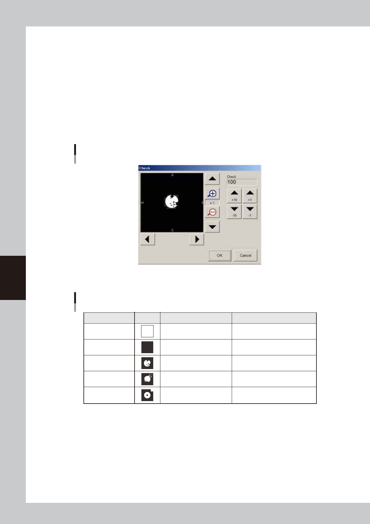
5. If the optimum threshold level could not be obtained, press the [Check] button. A binary image
appears on the vision monitor according to the current parameter settings as shown below.
Mark binary image
64536-N7-00
6. Adjust the threshold level as suggested below, so that the mark image is clearly displayed.
Binary image check
State Image Countermeasure Remarks
All white
All black
Noise within mark
Noise outside of mark
Other than mark in
search area
Increase the threshold level with
the arrow buttons.
Decrease the threshold with the
arrow buttons.
Increase the Cut Inner Noise level.
Increase the Cut Outer Noise level.
Reduce the Search Area size.
Adjust it till the mark is displayed.
Adjust it till the mark is displayed.
Recognition time becomes longer
as the Cut Inner Noise level is increased.
Recognition time becomes longer
as the Cut Outer Noise level is increased.
Refer to "Search Area"
explained previously.
63544-N7-00
7. Press the [Find Best] button again to find an optimum threshold level.
If the result is successful, next run the vision test. When no error occurs, advance to the next step.
8. If the vision test result is a fail, enter a larger value for the Tolerance parameter on the Mark Adjust
windows, then press the [Find Best] button again.
5-61
5
Creating the board data
7
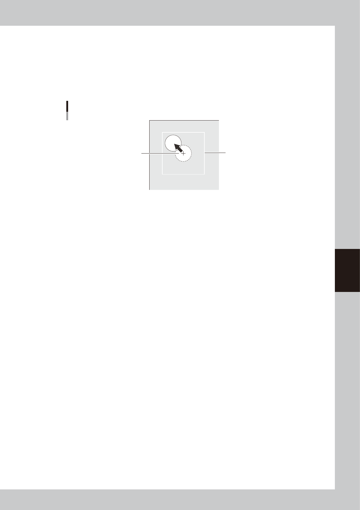
Check that the mark can be recognized even if it has moved.
Check that the mark can be recognized in any location within the search area.
1. Press the [Move Head] button to open the Move Head window.
2 .Use the arrow buttons to move the mark slightly from the center of the search area.
3. Return to the Mark Adjust window and run the vision test once more.
When no error occurs, the parameter settings are satisfactory. If an error still occurs, press the
[Check] button and readjust the binary level.
Search Area
Center of search area
Final check for mark recognition
63545-N7-00
8
Quit the Mark Adjust mode.
Press the [OK] button to quit the Mark Adjust mode.