YSD_Users_E.pdf - 第263页
5-74 5 Creating the board data 8. Height correction (option) As an optional function, this machine has a laser displacement meter to correct the dispensing or component mounting height relative to the board surface. This…

5-73
5
Creating the board data
7.2 Editing the dot dispense information
In the dot dispense information created as result of dispense distribution, "Qty." and "Head" data are input from
the component information and other data from the mount information.
Check the settings while referring to "4.9 Dot dispense parameters" in this chapter.
c
CAUTION
Performing dispense distribution will overwrite the current dispense data.
"-1" will be set to the sequence of the dot dispense information automatically when dispense distribution is
performed. This means that the software has selected the dispense sequence (see "6. Editing the dispense
sequence" in Chapter 4) automatically based on the registered component information and nozzle type.
If you need to perform dispense by the different sequence even if the quantity is the same, change the content
of a sequence No. which is not used for nozzle type of each head and manually change the sequence of the
corresponding data No. in the dot dispense information. Dispense will be performed by a different sequence
for that data No. only.
TIP
For example, if liquid must be dispensed on the convex surface of a board, prepare the dispense sequence for which
the lower target position, the height to permit the next task, and the upper target position have been changed.
5-74
5
Creating the board data
8. Height correction (option)
As an optional function, this machine has a laser displacement meter to correct the dispensing or component
mounting height relative to the board surface. This function is mainly used with the nozzle height correction
function using a touch sensor.
8.1 Creating the board data for height correction
Data format for the height correction function resembles the 2-point local fiducial mark setting. Make the
settings as explained below.
1
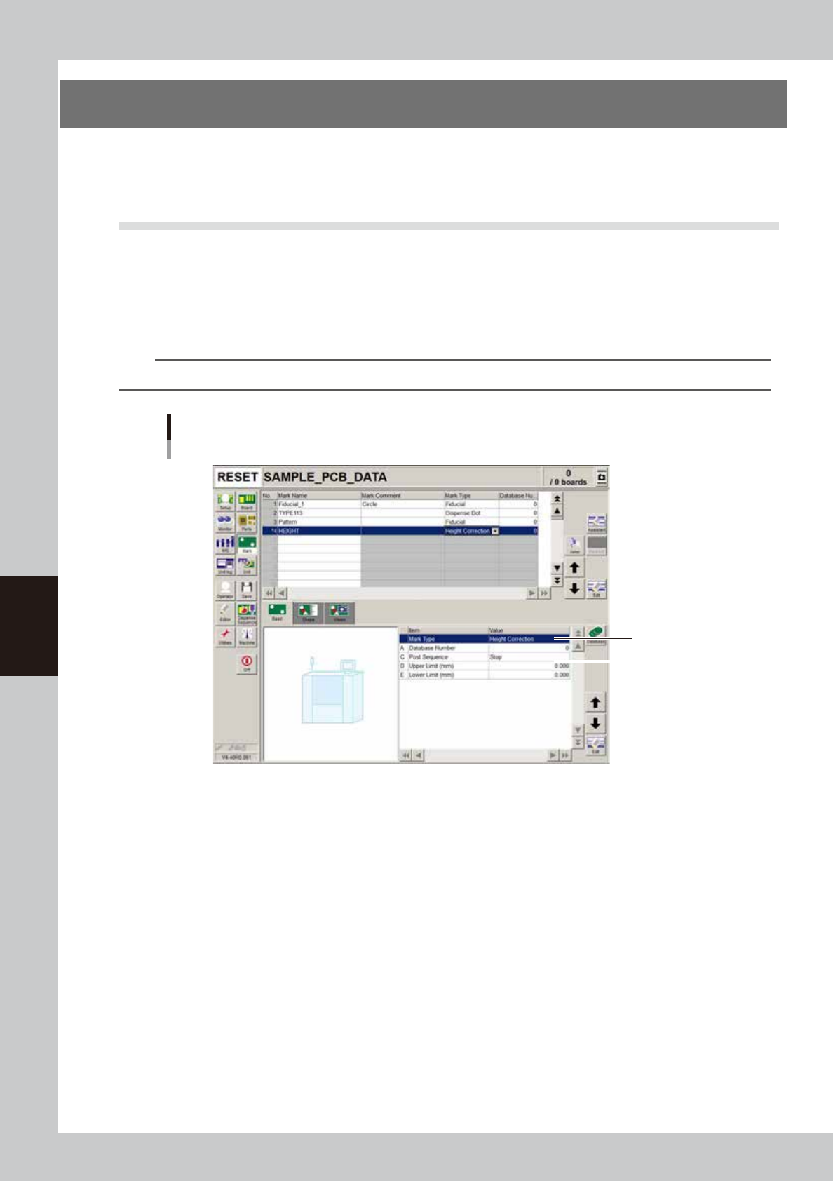
Set the Mark Type parameter.
On the [Mark]-[Basic] tab screen, enter the name in the Mark Name column and set the Mark Type
parameter to "Height Correction".
n
NOTE
When the Mark Type parameter is set to "Height Correction", the [Mark Adj] button is grayed out.
Step 1
Step 2
Mark screen
Setting Mark Type to "Height Correction"
64548-N7-00
2
Set the upper and lower limits.
Enter the upper and lower limits in millimeters to set an acceptable measurement result range. The
downward direction is positive (+) and the upward direction is negative (-), just as with the head
coordinate system.
5-75
5
Creating the board data
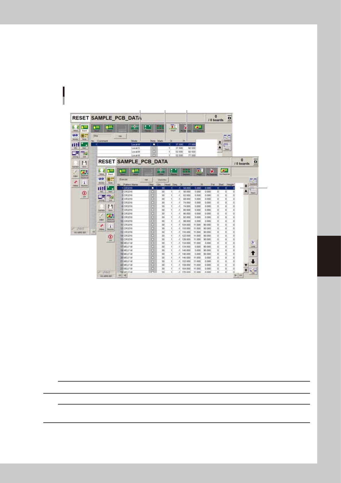
3
Set the height correction mode.
On the [Board]-[Height] tab screen, enter the comment in the Comment column and set the height
correction mode (number of height measurement points) in the Mode column.
• When measuring 1 point, set to "Local-M".
• When measuring 2 points to take an average, make the settings in 2 rows. Set the first row to
"Local-M" and the second row to "Local-S".
Mode setting
Height correction
Step 6
Step 3 Step4 Step5
64549-N7-00
4
Enter the mark No.
In the Mark column, enter the mark No. you set in steps 1 to 2.
5
Enter the XY coordinates.
Enter the XY coordinates to be measured. You can use the [Teach] button to open the Laser Height
window and enter the XY coordinates by teaching. After entering the XY coordinates, press the [Trace]
button in the Laser Height window to make a height measurement at that position and display the
results.
6
Enter the height correction No.
Select the [Dot Dispense] tab and, in the Height column, specify the number you set on the [Height] tab
in step 4.
n
NOTE
When using an average of 2-point measurements, enter the number for "Local-M".
n
NOTE
During automatic operation, the height correction measurement data is retained like local fiducial mark data. This
means that one item of height correction data is measured only once.