YSD_Users_E.pdf - 第377页
3-3 3 Periodic maintenance items 2. Monthly inspection This section mainly explains the cleaning and lubrication procedures after inspection. Inspect the ball screws and the guides on the X and Y axes. Checkpoints are li…
3-2
3
Periodic maintenance items
1.2 Checking the board clamp condition and operation
1.2.1 Checking the board clamp condition
Check the following points to see the board clamp condition.
1. The board is clamped without play when the board clamp is raised.
2. There is no clearance between the board and the board hold plate when the board clamp is raised.
3. The board is flush with the upper surface of the conveyor rails when the board clamp is raised.
4. The board clamp unit moves smoothly.
1.2.2 Checking the board clamp operation
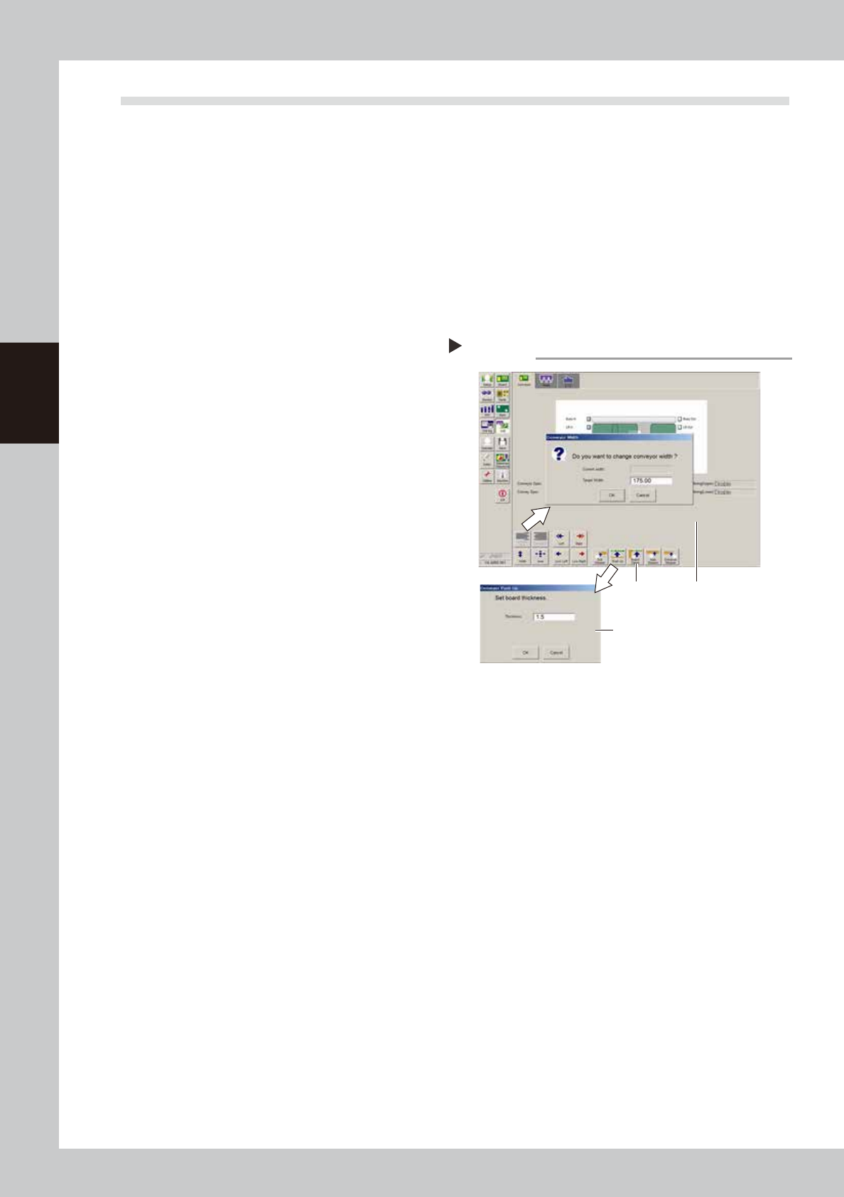
1
Open the [Unit] – [Conveyor] tab.
2
Press the [Width] button to set the
conveyor width.
In the "Target Width" box in the "Conveyor
Width" dialog box that appears, enter the
board width and press [OK]. The conveyor is
changed to the width that was just entered.
3
Press the [Push Up] button to enter
the board thickness.
In the dialog box that appears, enter the
board thickness and press [OK].
4
Press the [Board Clamp] button to
clamp the board.
5
Press the [Board Clamp] button
again to unclamp the board.
54303-N7-00
Repeat steps 4 and 5 to clamp and unclamp the
board to make sure the clamp unit operates
smoothly.
Checking the clamp operation
Step 2-5
Step4, 5
Step3
Step2
3-3
3
Periodic maintenance items
2. Monthly inspection
This section mainly explains the cleaning and lubrication procedures after inspection.
Inspect the ball screws and the guides on the X and Y axes. Checkpoints are listed below.
A grease spattering prevention cover is installed to the X and Y axes. Remove these covers when inspecting
the ball screw and guide.
n
Checkpoints
1. Any foreign matter adhering to the ball screws and linear guides?
2. Do the ball screws and linear guides have the correct amount of grease?
Check if grease has flowed off or splattered in the air failing to adhere. Also check if grease has discolored or
hardened.
3. Any abnormal sounds from the ball screws?
Press the emergency stop button. Then check for any abnormal sounds while pressing the head assembly or conveyor
table by hand along the X-axis or Y-axis back and forth.
n
Countermeasures
1. Ball screws and guides may be damaged when chips or debris bite into them. If chips or debris are adhering, wipe
them off along with the grease or remove with tweezers, etc.
2. Apply grease while referring to the "Cleaning and greasing" instructions described later.
3. Consult your YAMAHA sales office or representative when abnormal sounds occur even after trying the
countermeasures in the above steps 1 and 2.
c
CAUTION
When using grease, read and follow "Precautions when handling grease" described in "2. Preparing for maintenance
tasks" in Chapter 1.
c
CAUTION
If abnormal noise is emitted from the X or Y axis ball screw or guide, then contact our sales representative for
assistance. Disassembly and cleaning of the ball screw or guide by the user will void the warranty.
3-4
3
Periodic maintenance items
2.1 Cleaning and greasing the X and Y axes
This section describes the cleaning and lubrication procedures for the X and Y axis ball screws and guides.
Prepare a grease gun and specified grease (NSL).
2.1.1 Cleaning and greasing the X-axis ball screw
e
1
Press the emergency stop button.
The machine must be in emergency stop to
ensure safety during work.
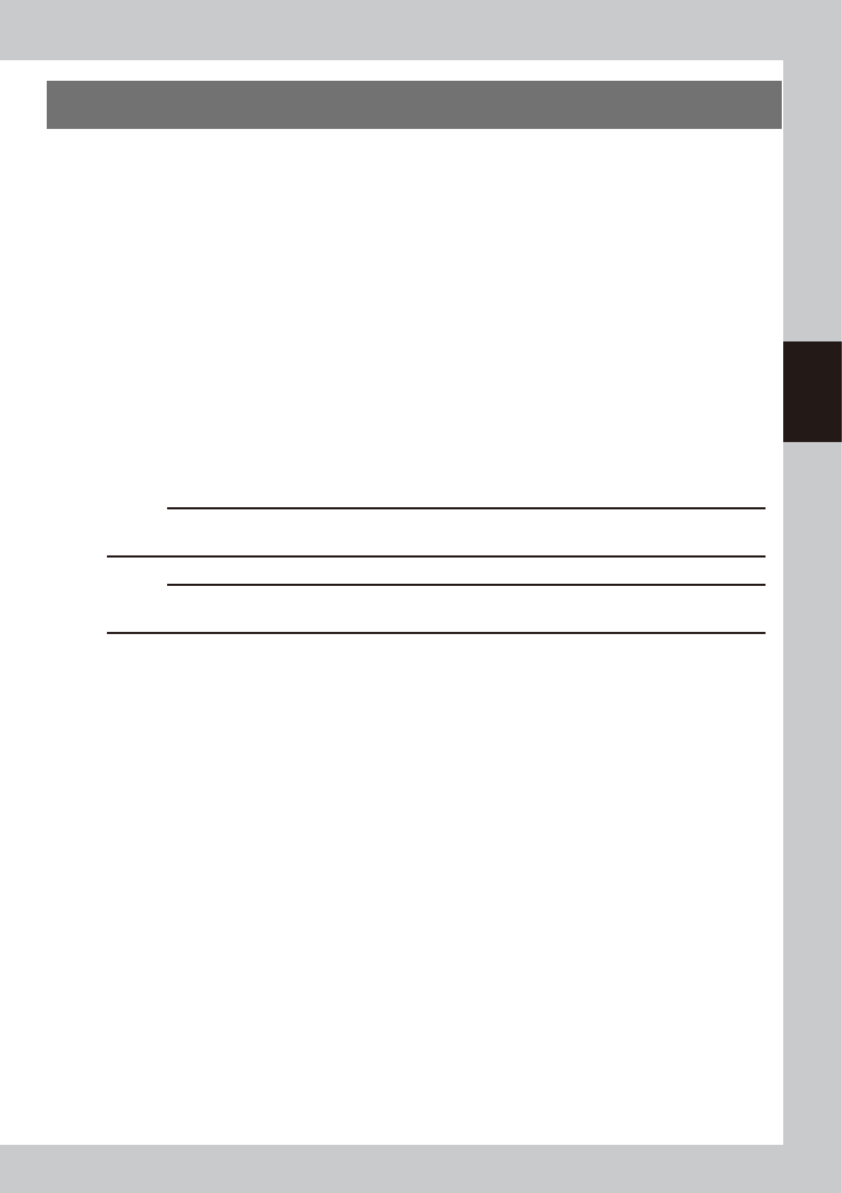
2
Remove the grease spattering
prevention cover.
1 Use a Phillips screwdriver to remove the
screws securing the left side of the
grease spattering prevention cover.
2. Move the head all the way to the left
side and remove the screws securing the
right side of the grease spattering
prevention cover.
3. Remove the grease spattering prevention
cover by pulling it to the right.
53305-N7-00
TIP
When reattaching the X-axis grease spattering
prevention cover, use the reverse order of the above
procedure.
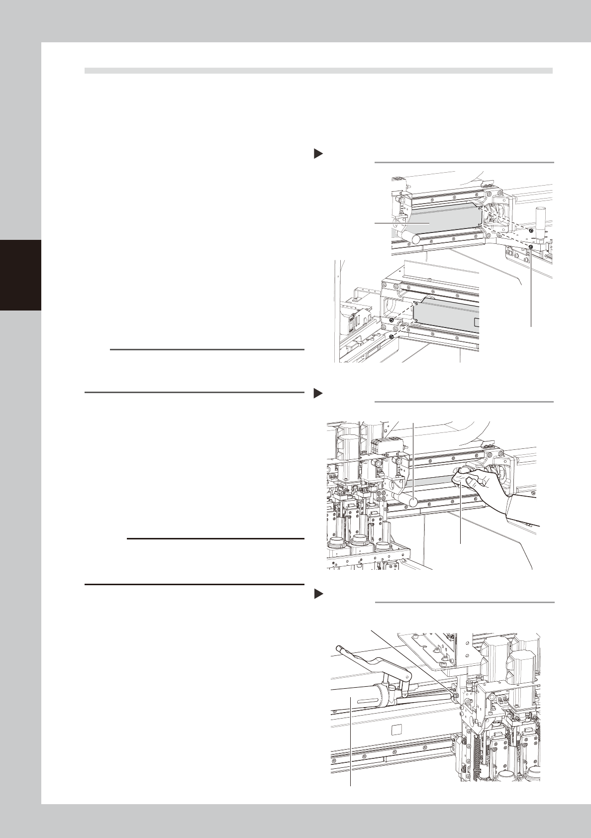
3
Clean the ball screws.
1. Using the handle, move the head to one
end of each axis.
2. Wipe away the old grease and dirt from
the ball screw with a lint-free cloth or
paper towel (for clean room use).
3. Move the head to the opposite end of
each axis and wipe the ball screw clean.
53306-N7-00
c
CAUTION
Wipe away the old grease and dirt in the lead groove
of the ball screw. Also check that no debris or residue
remains in the lead groove.
4
Apply grease to the ball screws.
Use the grease gun to supply the specified
grease (NSL) to the grease nipples. Then
move the head back and forth by hand
along each axis and wipe away excess
grease.
53307-N7-00
5
Reattach the covers.
Reattach the grease spattering prevention
covers in the reverse order of the removal
procedures.
Removing the X-axis ball screw cover
Step 2
Screw securing cover
Grease spattering
prevention cover
Cleaning the X-axis ball screw
Step 3
Head move handle
Paper wipe
Greasing the X-axis ball screw
Step 4
Grease nipple for
X-axis ball screw
Grease gun (with standard nozzle)