YSD_Users_E.pdf - 第40页
Chapter 1 Par t names and functions Contents 1. Machine main unit 1-1 2. Operation panel and data input unit 1-3 2.1 Operation panel buttons 1-4 2.2 Keyboard (option) 1-5 3. Head assembly 1-6 3.1 Dispenser head 1-6 3.2 N…
ii
About this manual
1.2 Page layout
The description below shows a typical page layout used in this manual.
2-34
2
Basic operation
4.3 Finishing board production
To finish board production, follow these steps.
1
Stop machine operation.
The re are three meth ods for stopping the machine.
1. Emergency stop button:
Press this button to trigger emergency stop. Do not use this button in normal operation.
e
2. [STOP] button (operation panel):
Pressing the [STOP] button stops the machine immediately. To resume operation, press the [START]
button on the operation panel.
3. [Cycle Stop] button:
Pressing this button stops the machine when dispense operation for the current board is completed.
4. [ConveyOut Stop] button:
Use this button when you want to finish production after adhesive is dispensed on the boards
currently on the conveyor. All boards on the conveyor are transferred to the downstream side after
adhesive dispensing, but new boards are not transferred from the upstream side.
c
CAUTION
Do not press the emergency stop button during operation except in case of emergency.
2
Reset the operation.
Press the [RESET] button on the operation panel. The machine stops operation immediately and returns
to the board production standby status.
3
Press the [Off] button.
Press the [Off] button located in the button area.
[Off] button
[Off] button
64223-N7-00
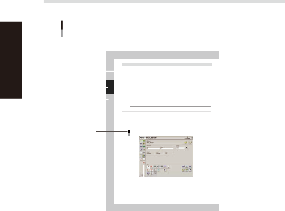
Typical page layout
Step
Chapter number
Chapter title
Substep or
description of step
Figure, picture
or table caption
Note, Caution
or Warning
63000-N7-00
n
Step
This describes the procedure for each operation.
n
Substep or description of step
This provides detailed information on each step.
n
Figure or table caption
This is the title of the figure or table and appears at the upper left.
n
Note, Caution or Warning
These are explained in detail in "Safety instructions".

Chapter 1 Part names and functions
Contents
1. Machine main unit 1-1
2. Operation panel and data input unit 1-3
2.1 Operation panel buttons 1-4
2.2 Keyboard (option) 1-5
3. Head assembly 1-6
3.1 Dispenser head 1-6
3.2 Nozzle types 1-7
3.2.1 Two-shot nozzles 1-7
3.2.2 One-shot nozzles 1-8
3.2.3 Narrow-pitch type nozzles 1-9
3.3 Dot plate 1-10
3.4 Dot station (option) 1-11
4. Front panel switches 1-12
5. Conveyor unit 1-13
6. Axis configuration 1-14
7. Air regulator unit 1-15
8. Connection between machines 1-16
8.1 PREVIOUS INTERFACE connector 1-17
8.2 NEXT INTERFACE connector 1-18
9. Power connection terminals 1-19
1-1
1
Part names and functions
1. Machine main unit
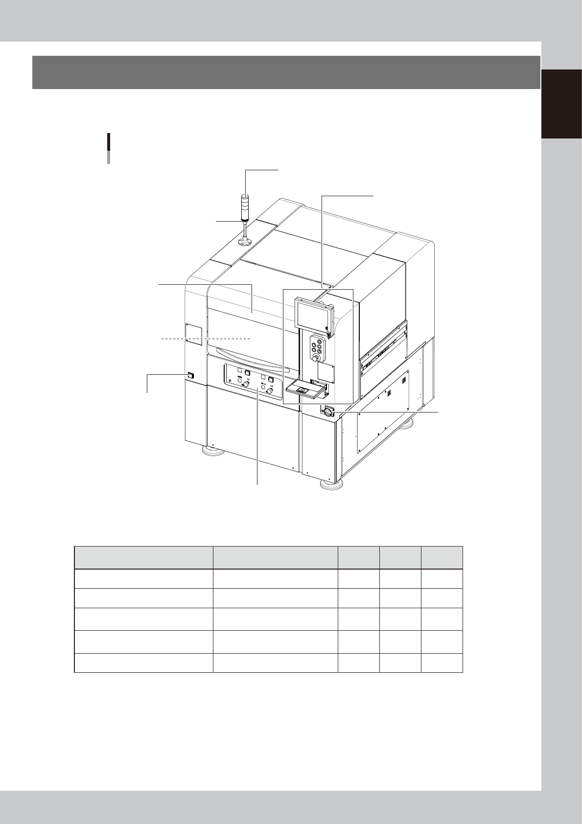
A machine has the following configurations after installation is complete.
Names and functions of major parts of the main unit are illustrated below.
Main unit
Main power switch
Pressure gauge
Operation panel and data input unit
Signal light (signal tower)
Buzzer
Head assembly
Front operation panel
Safety cover
63100-N7-10
n
Signal light (signal tower)
Indicates current operating conditions of the machine with a green, yellow and red lamp.
Machine status Example Green
Red/
White
Yellow/
Blue
Warm-up, AUTO operation ON
Emergency stop ON
System error
--- Buzzer ON ---
• Overcurrent
• Secondary limit exceeded
ON
Operation error, board data error
--- Buzzer ON ---
• Pickup error, recognition error
• Data check error, etc.
ON
Materials unusable Adhesive ON
n
Buzzer
This buzzer sounds if an error or abnormal operation has occurred. (Volume can be adjusted by turning the buzzer ring
right or left.)
n
Safety cover
Opening this cover triggers emergency stop so the machine operation immediately stops. Keep this cover closed during
operation.