YSD_Users_E.pdf - 第42页
1-2 1 Part names and functions n Pressure gauge See “7. Air pressure regulator unit” in this chapter . • Supply air pressure (upper reading): 0.40MP a (0.40MP a to 0.41MP a) • Pressure-drop detection level (lower reading…
1-1
1
Part names and functions
1. Machine main unit
A machine has the following configurations after installation is complete.
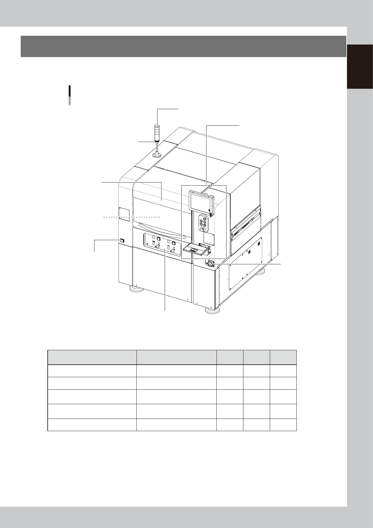
Names and functions of major parts of the main unit are illustrated below.
Main unit
Main power switch
Pressure gauge
Operation panel and data input unit
Signal light (signal tower)
Buzzer
Head assembly
Front operation panel
Safety cover
63100-N7-10
n
Signal light (signal tower)
Indicates current operating conditions of the machine with a green, yellow and red lamp.
Machine status Example Green
Red/
White
Yellow/
Blue
Warm-up, AUTO operation ON
Emergency stop ON
System error
--- Buzzer ON ---
• Overcurrent
• Secondary limit exceeded
ON
Operation error, board data error
--- Buzzer ON ---
• Pickup error, recognition error
• Data check error, etc.
ON
Materials unusable Adhesive ON
n
Buzzer
This buzzer sounds if an error or abnormal operation has occurred. (Volume can be adjusted by turning the buzzer ring
right or left.)
n
Safety cover
Opening this cover triggers emergency stop so the machine operation immediately stops. Keep this cover closed during
operation.

1-2
1
Part names and functions
n
Pressure gauge
See “7. Air pressure regulator unit” in this chapter.
• Supply air pressure (upper reading): 0.40MPa (0.40MPa to 0.41MPa)
• Pressure-drop detection level (lower reading): 0.33MPa
n
Head assembly
Dispenses adhesive using the dispenser heads installed at the lower end of the head assembly. It is also equipped with a
camera that recognizes marks on the boards. (See "3. Head assembly" in this chapter.)
n
Main power switch
Turns the machine power on or off. The power is on when this switch is turned to the right.
c
CAUTION
Wait at least 2 seconds before turning this power switch back on after turning it off.
n
Front operation panel
See “4. Front operation panel” in this chapter.
1-3
1
Part names and functions
2. Operation panel and data input unit
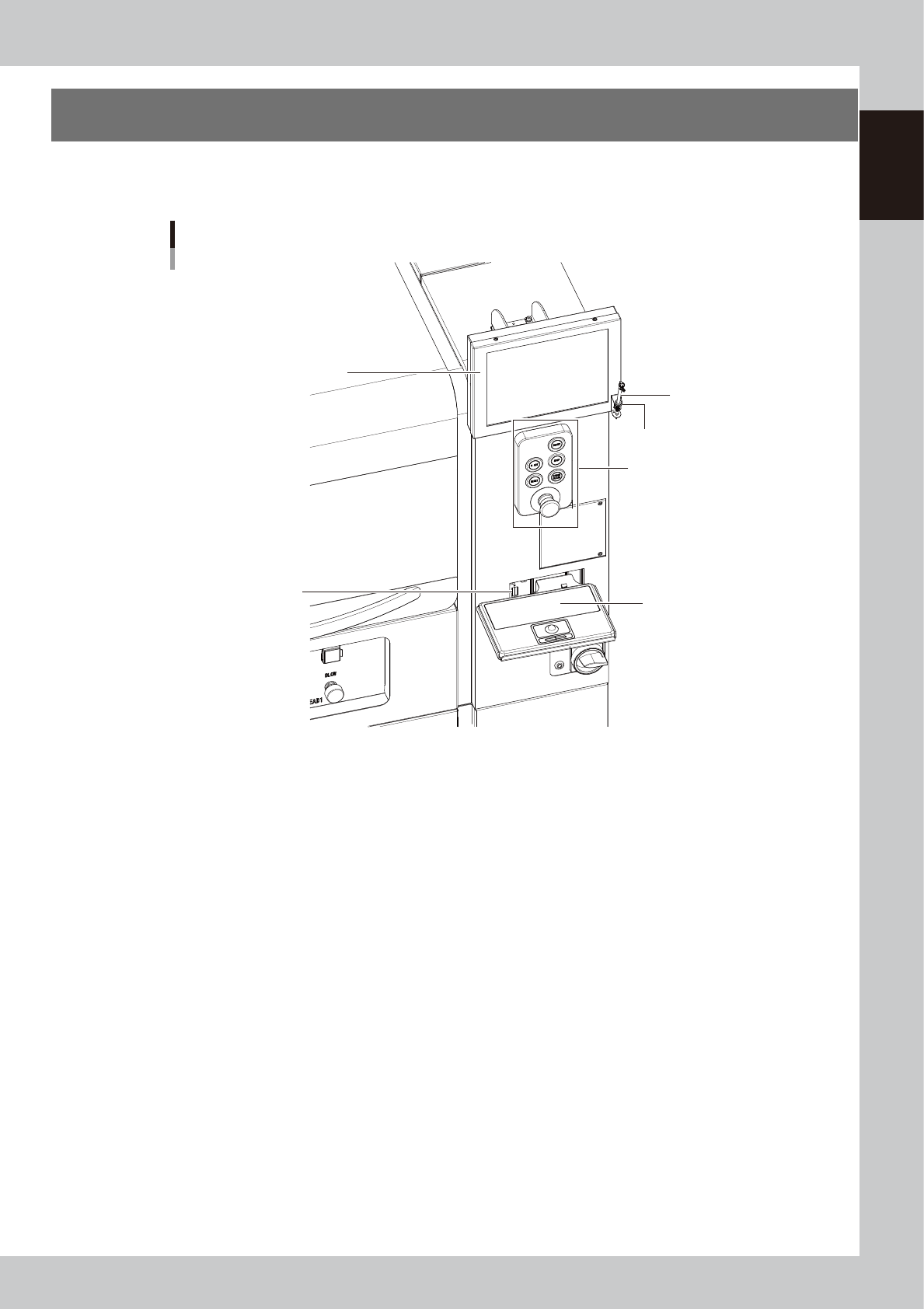
Operation panels and operation display screens for data inputs are provided at both the front and rear of
the machine. The functions of these units are explained below.
Operation panel and data input unit
Operation panel buttons
Touch pen
Touch pen holder
Keyboard (option)
Keyboard connector
Operation display
63101-N7-10