YSD_Users_E.pdf - 第56页
1-16 1 Part names and functions 8. Connection between machines The dispenser ejects the board when it receives a signal from the machine in the next process, and then sends a signal to the machine in the preceding proces…
1-15
1
Part names and functions
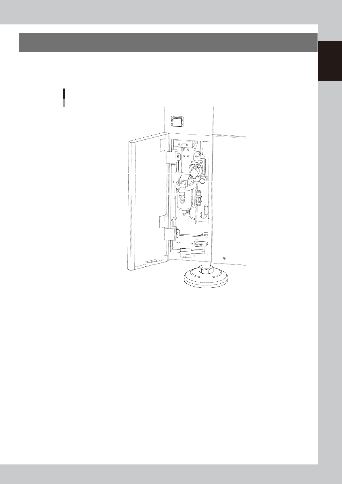
7. Air regulator unit
The air pressure regulator adjusts the pressure of compressed air supplied to the pneumatically driven
components of the machine and is located behind the front lower left panel of the machine. The air pressure
regulator must be correctly set to maintain the optimum air pressure.
Air regulator unit
Air pressure supply/
shutoff switch
Source air connector
Pressure regulator
Behind lower left panel
Air pressure gauge
63114-N7-00
• Air pressure gauge
Shows the air pressure setting (upper display) and pressure-drop detection level (lower display).
The air pressure display is green in normal condition but changes to red when a pressure drop is detected.
Supply air pressure: 0.45MPa or more
Air pressure setting: 0.40Mpa (0.40MPa to 0.41MPa)
Pressure-drop detection level: 0.33MPa
• Air pressure supply/shutoff switch
Turning this switch to the right shuts off air supply and exhausts the air that remains inside the air path of the machine.
• Pressure regulator
Use to adjust the air pressure so that air pressure gauge reads 0.4MPa (at a consumption rate of 60NL per minute).
• Source air connector
Prepare an air hose with an inner diameter of at least 8 mm having a 30SH socket (Nitto Koki, or equivalent), and
connect it to this connector. Use dry, clean air passed through an air filter.
1-16
1
Part names and functions
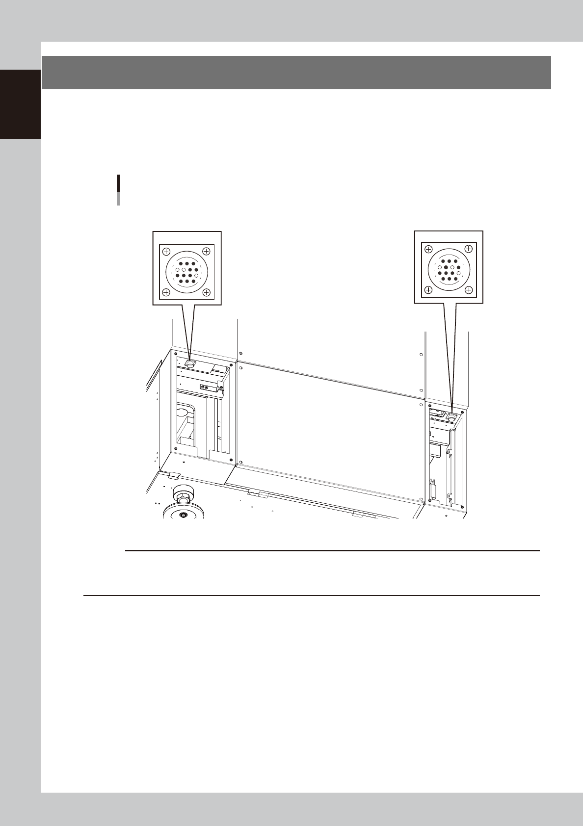
8. Connection between machines
The dispenser ejects the board when it receives a signal from the machine in the next process, and then
sends a signal to the machine in the preceding process to request another board. The interface connector
labeled "NEXT INTERFACE" connects to the machine in the next process, and the interface connector labeled
"PREVIOUS INTERFACE" connects to the machine in the preceding process.
These connectors are located behind the left and right panels on the rear of the machine.
PREVIOUS INTERFACE
7
12
4
8
1
14
11
3
NEXT INTERFACE
14
11
12
7
4
8
3
1
Gate signal connectors
Right-to-left flow example
Rear of machine (behind left and right panels)
63115-N7-10
c
CAUTION
· If the machine in the preceding process is a VIOS machine (YV100 II, etc.), a dedicated cable will be needed. (Refer
to the machine specifications for detailed information.)
· The “NEXT” and “PREVIOUS” connector positions are reversed in the case of left-to-right board flow.
1-17
1
Part names and functions
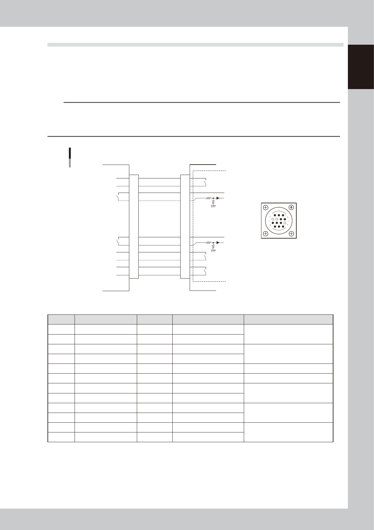
8.1 PREVIOUS INTERFACE connector
When the following three conditions are met, the PREVIOUS INTERFACE circuit in the machine allows the next
board to be carried in.
1. Machine is ready for carrying in a board (BUSY OUT: ON)
2. Board carry-in signal is input from the upstream machine. (BA IN [N0100321]: ON)
3. Automatic operation signal is input from the upstream machine. (UR IN [N0100322]: ON)
n
NOTE
• When the automatic operation signal (UR IN) from the loader turns off during transfer of a board, the machine
temporarily stops carrying in the board.
• When the board being carried in is detected by the entrance sensor, the BUSY OUT signal turns off.
• Carrying in the board is finished when both the BUSY OUT and BA IN turn off.
1
2
3
4
5
6
7
8
9
10
11
12
13
14
BUSY OUT
(T01000E4)
+24V
+24V
LR OUT
(T01000E7)
UR IN
(N0100322)
BA IN
(N01000321)
Signal input during
board carry-in
Signal output to
request board
carry-out
Signal output during
automatic operation
Signal input during
automatic operation
LE OUT
(T0100031)
Signal input during
waiting for board
between machines
I/O BOARD
7
12
4
8
1
14
11
3
PREVIOUS INTERFACE circuit
PREVIOUS INTERFACE on this machineUpstream machine
PREVIOUS INTERFACE
connector
AMP 206043-1
(14-pin receptacle)
63116-N7-00
n
Board transfer signal specifications (PREVIOUS INTERFACE)
Pin No. Signal name Address I/O specifications Signal specifications
1 BUSY OUT T01000E4 Relay contact output
Signal output during board carry-in
2 BUSY OUT T01000E4 Relay contact output
3 +24V Input common (+24V)
Signal input to request board carry-out
4 BA IN N0100321 Voltage input
5 NC (with dummy pin) (Prevents misinsertion.)
6 to 8 NC
9 +24V Input common (+24V)
Signal input during automatic
operation
10 UR IN N0100322 Voltage input
11 LR OUT T01000E7 Relay contact output
Signal output during automatic
operation
12 LR OUT T01000E7 Relay contact output
13 LE OUT T0100031 Zero voltage output
Signal output during waiting for board
between machines
14 LE OUT T0100031 Zero voltage output