YSD_Users_E.pdf - 第59页
1-19 1 Part names and functions 9. Power connection ter minals The power connection terminals are located inside the lower left panel on the rear of the machine. Connect the power cable leads as shown below to the primar…
1-18
1
Part names and functions
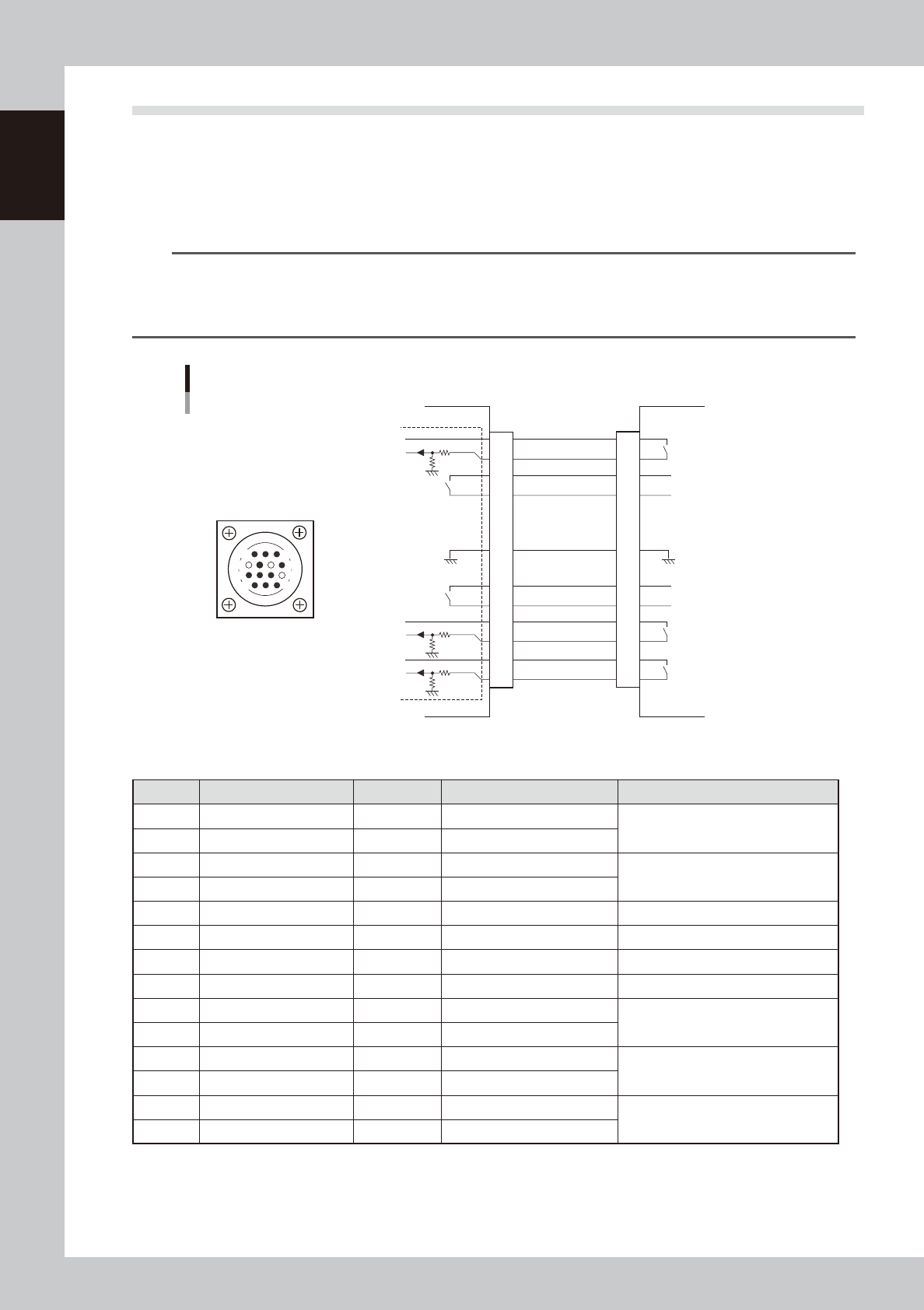
8.2 NEXT INTERFACE connector
When the following three conditions are met, the NEXT INTERFACE circuit in the machine allows the board to
be carried out.
1. Machine is ready for carrying out a board (BA OUT: ON)
2. Board carry-in signal is input from the downstream machine. (BUSY IN [N0100320]: ON)
3. Automatic operation signal is input from the downstream machine. (LR IN [N0100323]: ON)
n
NOTE
• When the automatic operation signal (LR IN) from the downstream machine turns off during transfer of a board,
the machine stops temporarily carrying out the PC.
• When the board being carried out is detected by the exit sensor, the BA OUT signal turns off.
• Carrying out the board is finished when both the BUSY IN and BA OUT turn off.
1
2
3
4
5
6
7
8
9
10
11
12
13
14
BUSY IN
(N0100320)
+24V
+24V
UR OUT(T01000E6)
LR IN
(N0100323)
+24V
LE IM
(N0100324)
BA OUT
(T01000E5)
Signal output during
board carry-in
Signal input to request
board carry-out
Signal input during
automatic operation
Signal output during
automatic operation
Signal output during
waiting for board
between machines
I/O BOARD
GND GND
14
11
12
7
4
8
3
1
NEXT INTERFACE circuit
NEXT INTERFACE
connector
NEXT INTERFACE on this machine
Downstream machine
AMP 206043-1
(14-pin receptacle)
63117-N7-00
n
Board transfer signal specifications (NEXT INTERFACE)
Pin No. Signal name Address I/O specifications Signal specifications
1 +24V Input common (+24V)
Signal input during board carry-in
2 BUSY IN N0100320 Voltage input
3 BA OUT T01000E5 Relay contact output
Signal output to request board carry-out
4 BA OUT T01000E5 Relay contact output
5 NC
6 NC (with dummy pin) (Prevents misinsertion.)
7
8 NC
9 UR OUT T01000E6 Relay contact output
Signal output during automatic
operation
10 UR OUT T01000E6 Relay contact output
11 +24V Input common (+24V)
Signal input during automatic
operation
12 LR IN N0100323 Voltage input
13 +24V Input common (+24V)
Signal input during waiting for board
between machines
14 LE IN N0100324 Voltage input
1-19
1
Part names and functions
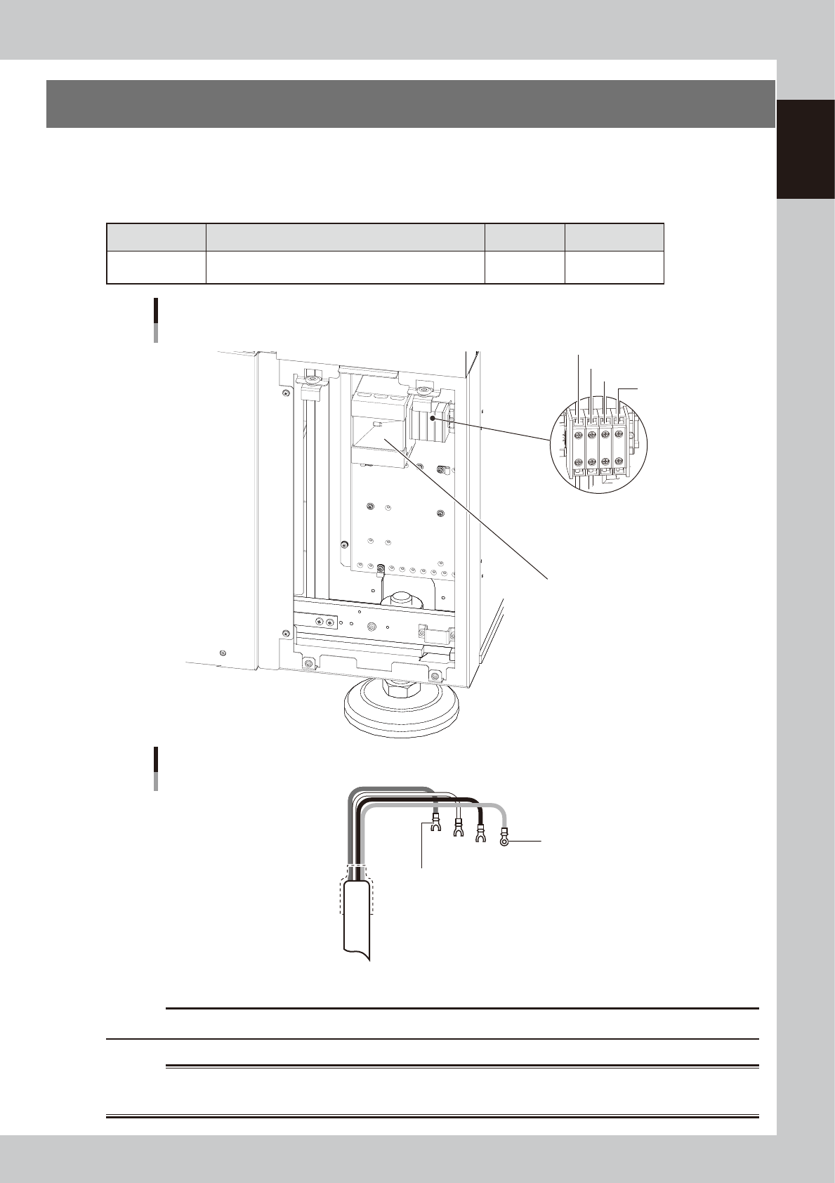
9. Power connection terminals
The power connection terminals are located inside the lower left panel on the rear of the machine.
Connect the power cable leads as shown below to the primary terminals L1, L2 and L3 on the main breaker
and the ground terminal on the main unit chassis.
n
Power supply specifications
Machine name Power Frequency Power capacity
YSD
3-phase AC
200 / 208/ 220 / 240 / 380 / 400 / 416V (±10%)
50/60Hz 7.0KVA
Power input terminal
Main breaker
Power input terminal
L1
L2
L3
PE
63118-N7-00
Ring-tongue crimp terminal
Fork-tongue crimp terminal
Power cable example
L1
L2
L3
PE
L=100mm
63119-N7-10
c
CAUTION
Use a power cable whose conductor cross section is 3.3 mm2 or more.
w
WARNING
TO AVOID THE RISK OF ELECTRICAL SHOCK, ENSURE THAT THE POWER SOURCE IS OFF BEFORE CONNECTING THE POWER
CABLE. ALSO MAKE SURE THAT THE GROUND CABLE IS SECURELY CONNECTED TO THE MACHINE.

Chapter 2 Basic operation
Contents
1. Before operation 2-1
1.1 Starting the machine 2-1
1.2 Canceling emergency stop 2-3
1.3 Clearing an error 2-4
1.4 Turning off the machine power 2-5
2. Operation screen and buttons 2-7
2.1 Basic configuration of operation screen 2-7
2.2 Setup screen 2-10
2.3 Unit screen 2-12
3. Machine operation from start to finish 2-16
3.1 Pre-operation check 2-17
3.2 Selecting the board data 2-18
3.3 Changing the conveyor unit setup 2-19
3.3.1 Conveyor unit setup flow 2-19
3.3.2 Changing the conveyor width 2-20
3.3.3 Adjusting the board hold plates 2-21
3.3.4 Arranging the push-up pins 2-22
3.4 Head unit setup 2-24
3.5 Starting and warming up the machine 2-27
3.6 Bleeding the nozzle air 2-29
3.7 Performing a dispensing test 2-32
3.8 Starting board production 2-34
3.9 Displaying the production monitors 2-35
3.10 Finishing board production 2-44
4. Basic tasks for optional units 2-46
4.1 Low-liquid sensor 2-46
4.1.1 Adjusting the low-liquid sensor 2-48
4.2 Dot station 2-50
4.2.1 Replacing the paper 2-50
4.3 Laser displacement meter 2-52
4.3.1 Initialization 2-52