YSD_Users_E.pdf - 第76页
2-16 2 Basic operation 3 . Machine operation from star t to finish T he following is the basic flow of the machine oper ation from start to finish. Since the title of each step is the same as the heading of each section …
2-15
2
Basic operation
n
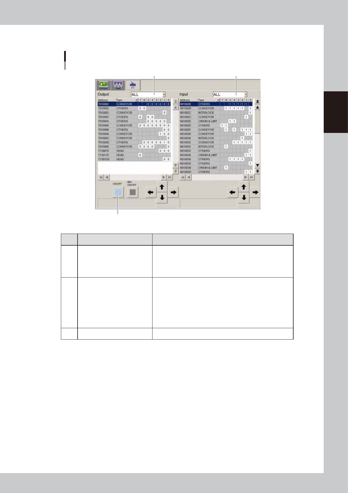
Manual I/O operation
[Unit] – [I/O] screen
1
2
3
64234-N7-00
Button name Function
1 Select output display group
Select the output group for display in the "Output" status list. The
following groups can be selected:
• CONV (conveyor)
• HEAD
• OTHERS
2 Select input display group
Select the input group for display in the "Input" status list. The
following groups can be selected:
• INTLCK (interlock)
• CONV (conveyor)
• HEAD
• SPARE
• SRV (servo origin limit)
• OTHERS
3 ON/OFF Turns the selected valve on or off.
2-16
2
Basic operation
3. Machine operation from start to finish
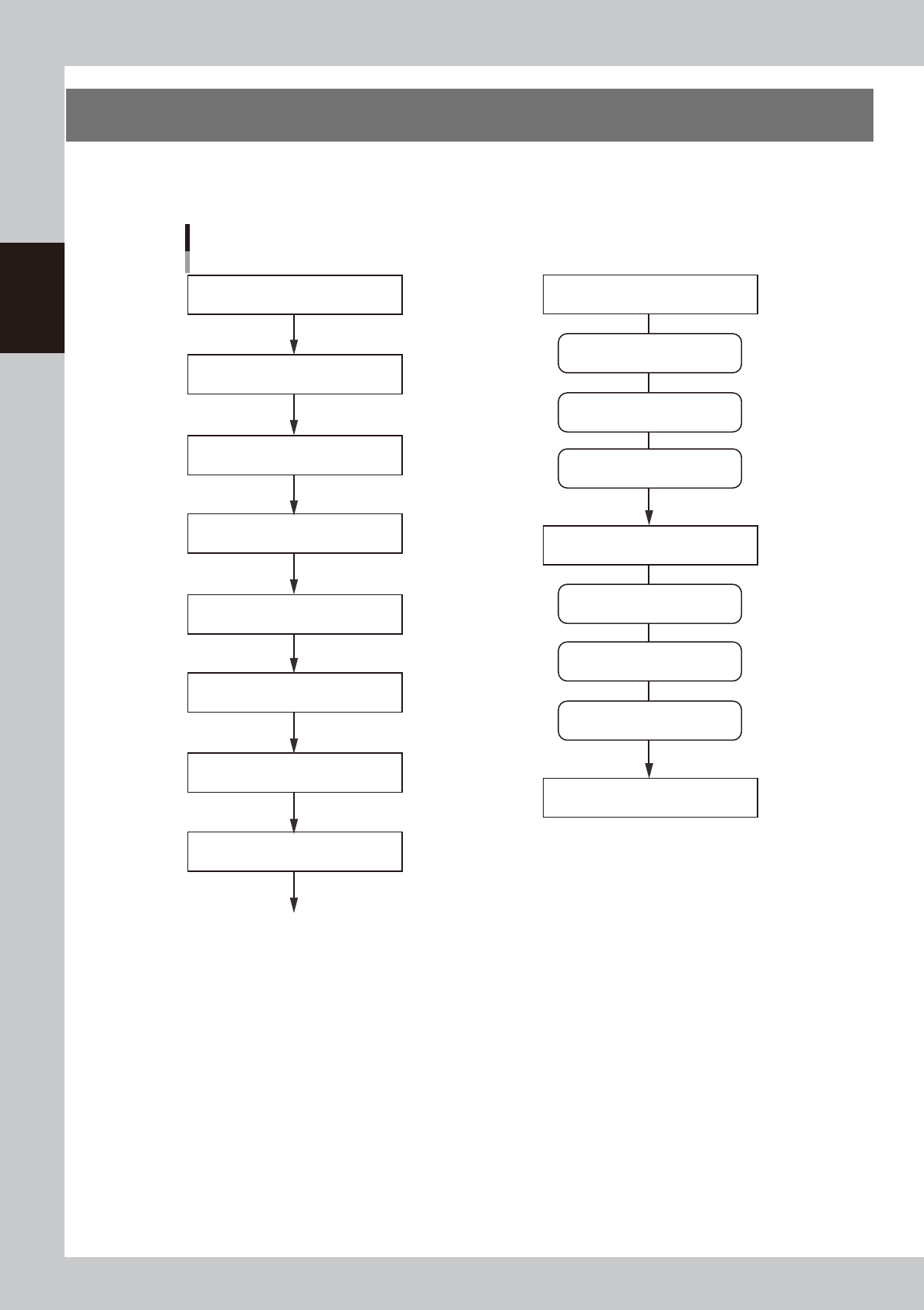
The following is the basic flow of the machine operation from start to finish. Since the title of each step is the
same as the heading of each section in this manual, refer to the table of contents to find the information on the
steps you want to know.
Flow of machine operation from start to finish
3.6 Bleeding the nozzle air
1.1 Starting the machine
3.1 Pre-operation check
3.2 Selecting the board data
3.5 Starting and warming up the machine
3.4 Setting up the head unit
Optimum pressure setting
Do this just before starting board production
3.7 Performing a dispensing test
3.3 Changing the conveyor unit setup
3.8 Starting board production
To the step for “Starting board production”
Remove syringes
Dispense for position correction
Predispense
Remove back-up pins
Clean nozzles
1.4 Turning off the machine power
Dispense on board
3.10 Finishing board production
Temperature regulator ON
Power ON
Power OFF
63201-N7-10
2-17
2
Basic operation
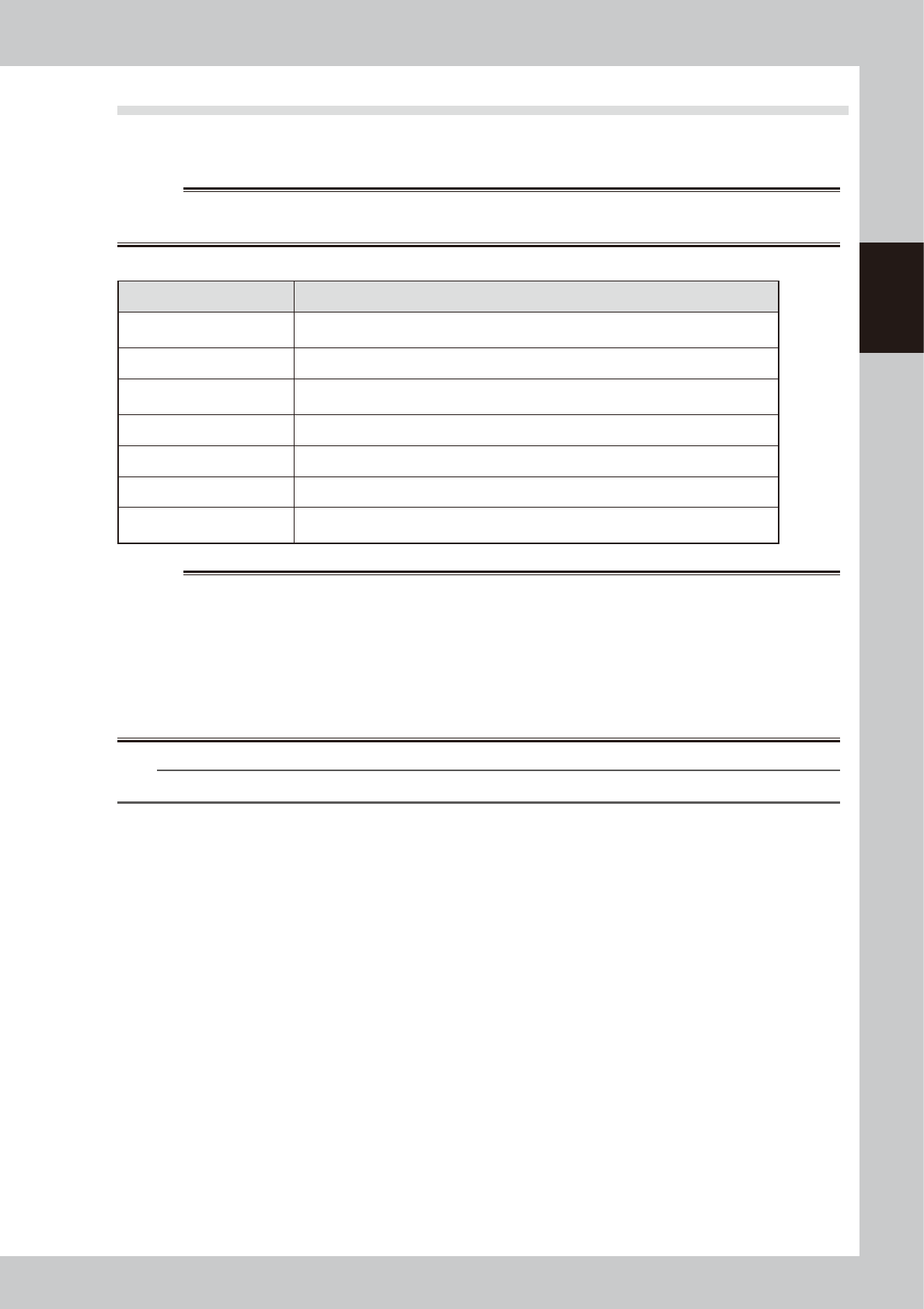
3.1 Pre-operation check
The table below shows checkpoints you should make before turning the power on.
e
w
WARNING
WHEN MAKING CHECKS WITH THE POWER TURNED ON, BE SURE TO MAKE SURE THAT THE EMERGENCY STOP BUTTON IS
PRESSED.
n
Pre-operation checklist
Check item Checkpoint
Power supply
Check that the specified power is connected to the power supply box located on the front
lower right of the machine.
Emergency stop button Check that the emergency stop button is pressed.
Conveyor
Check that no foreign matter or debris is on the conveyor.
Check that no parts of the conveyor unit interfere with each other such as the push-pins.
Nozzle Check that there is no dirt, deformation or clogging in the nozzle.
Head Check that each nozzle is correctly installed to the head.
Safety cover Check that the safety cover is closed.
Air
Check that the air pressure gauge on the front lower left panel of the machine reads
0.4MPa. (Make this check when the power is ON.)
w
WARNING
THE SIGNAL LIGHT (OR WARNING LAMP) IS AN IMPORTANT DEVICE THAT INDICATES THE MACHINE STATUS. BEFORE
BEGINNING ANY OPERATION, BE SURE TO CHECK THAT THE SIGNAL LIGHT SHOWS THE CORRECT MACHINE STATUS AS
FOLLOWS:
GREEN: MACHINE IS IN AUTOMATIC OPERATION.
YELLOW: ERROR OR INTERLOCK HAS OCCURRED.
RED: MACHINE IS IN EMERGENCY STOP.
NEVER ALLOW ANY PART OF THE BODY OR ANY OBJECT TO ENTER THE MOVEMENT RANGE OF THE HEAD ASSEMBLY WHILE
THE GREEN LAMP IS LIT.
n
NOTE
Before using adhesive, take it out of the storage location and allow it to return to the temperature in the machine.