YSD_Users_E.pdf - 第78页
2-18 2 Basic operation 3.2 Selecting the board data Select and load the board data to use for production. When the selected board data uses a heater , the temperature regulator also turns on. Select the board data as fol…
2-17
2
Basic operation
3.1 Pre-operation check
The table below shows checkpoints you should make before turning the power on.
e
w
WARNING
WHEN MAKING CHECKS WITH THE POWER TURNED ON, BE SURE TO MAKE SURE THAT THE EMERGENCY STOP BUTTON IS
PRESSED.
n
Pre-operation checklist
Check item Checkpoint
Power supply
Check that the specified power is connected to the power supply box located on the front
lower right of the machine.
Emergency stop button Check that the emergency stop button is pressed.
Conveyor
Check that no foreign matter or debris is on the conveyor.
Check that no parts of the conveyor unit interfere with each other such as the push-pins.
Nozzle Check that there is no dirt, deformation or clogging in the nozzle.
Head Check that each nozzle is correctly installed to the head.
Safety cover Check that the safety cover is closed.
Air
Check that the air pressure gauge on the front lower left panel of the machine reads
0.4MPa. (Make this check when the power is ON.)
w
WARNING
THE SIGNAL LIGHT (OR WARNING LAMP) IS AN IMPORTANT DEVICE THAT INDICATES THE MACHINE STATUS. BEFORE
BEGINNING ANY OPERATION, BE SURE TO CHECK THAT THE SIGNAL LIGHT SHOWS THE CORRECT MACHINE STATUS AS
FOLLOWS:
GREEN: MACHINE IS IN AUTOMATIC OPERATION.
YELLOW: ERROR OR INTERLOCK HAS OCCURRED.
RED: MACHINE IS IN EMERGENCY STOP.
NEVER ALLOW ANY PART OF THE BODY OR ANY OBJECT TO ENTER THE MOVEMENT RANGE OF THE HEAD ASSEMBLY WHILE
THE GREEN LAMP IS LIT.
n
NOTE
Before using adhesive, take it out of the storage location and allow it to return to the temperature in the machine.
2-18
2
Basic operation
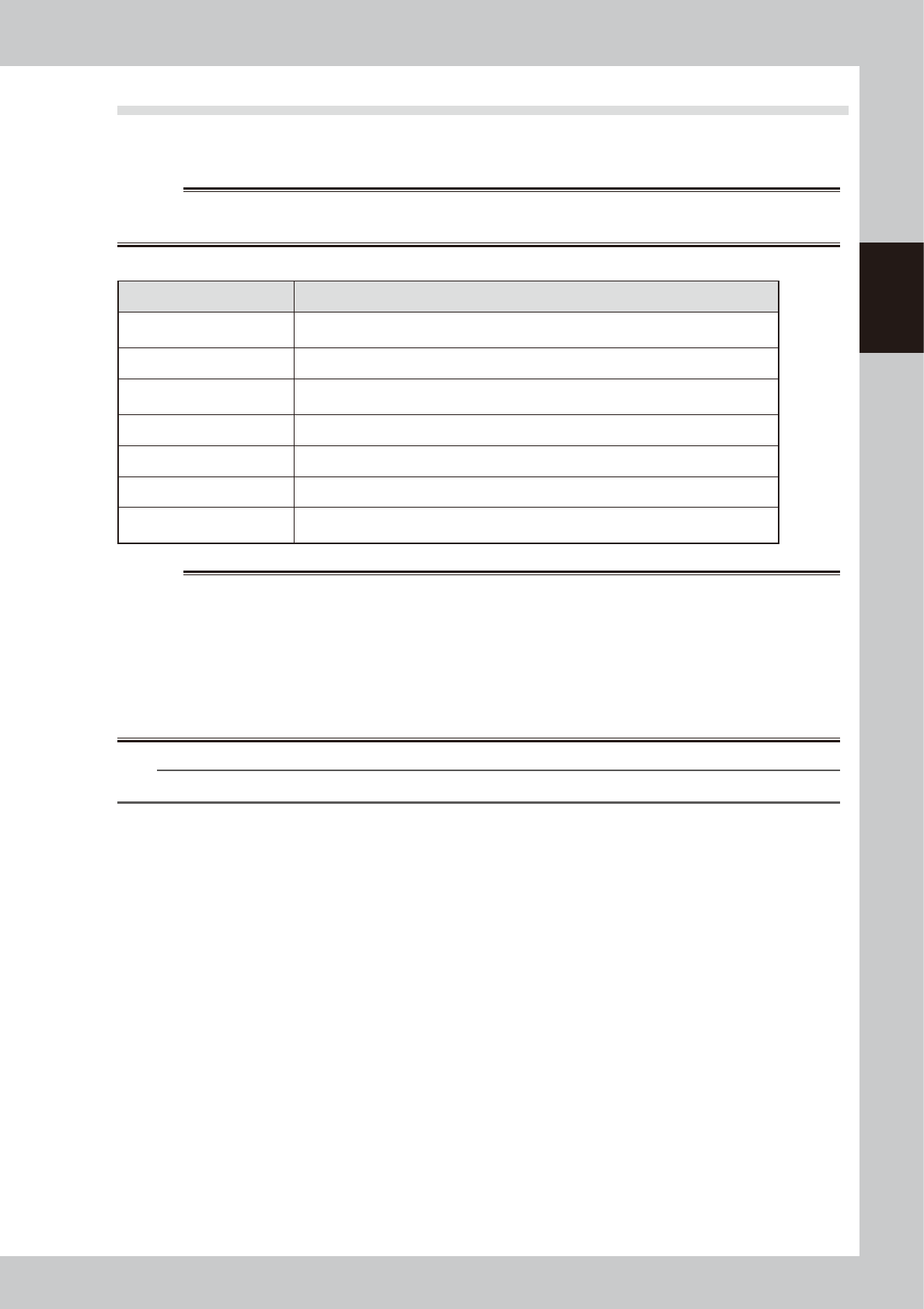
3.2 Selecting the board data
Select and load the board data to use for production. When the selected board data uses a heater, the
temperature regulator also turns on.
Select the board data as follows:
1. On the Setup screen, press the [Board] button to display the list of the registered board data.
2. Line up the cursor with the board name for production and press the [Select] button. The selected
board data will be loaded.
Selecting the board name
Select the board from the list of registered board data
The selected board name appears here.
64235-N7-00
2-19
2
Basic operation
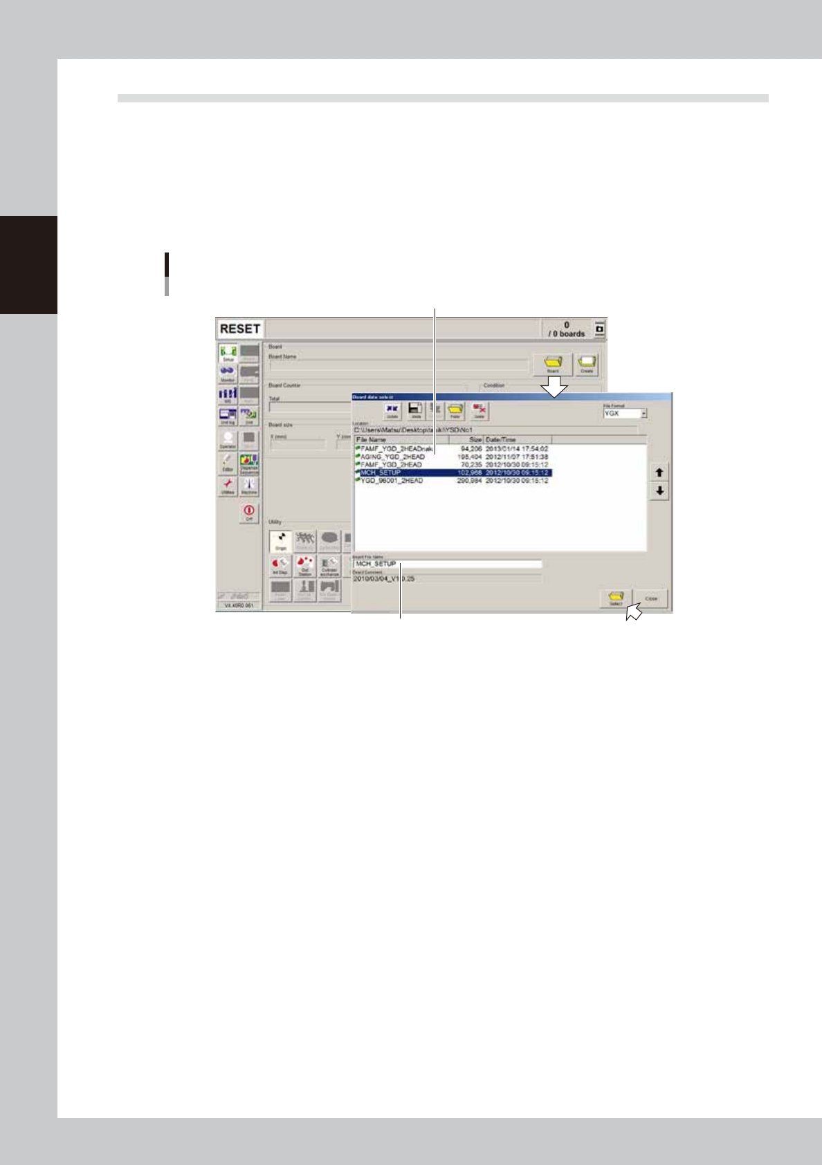
3.3 Changing the conveyor unit setup
When the board type to be produced is changed, the conveyor unit must be set up correctly according to that
board type. This section describes how to change the conveyor unit setups.
Board clamping method
The board clamping method should be set to "Edge Clamp". Open the [Board] - [Board] tab and make sure that the
"Board Fix Device" parameter is set to "Edge Clamp". If not, set it to "Edge Clamp". With this method, the board is
clamped with support from the edges and also with push-up pins.
[Board] tab grid showing Board clamping method
Board clamping method
64209-N7-00
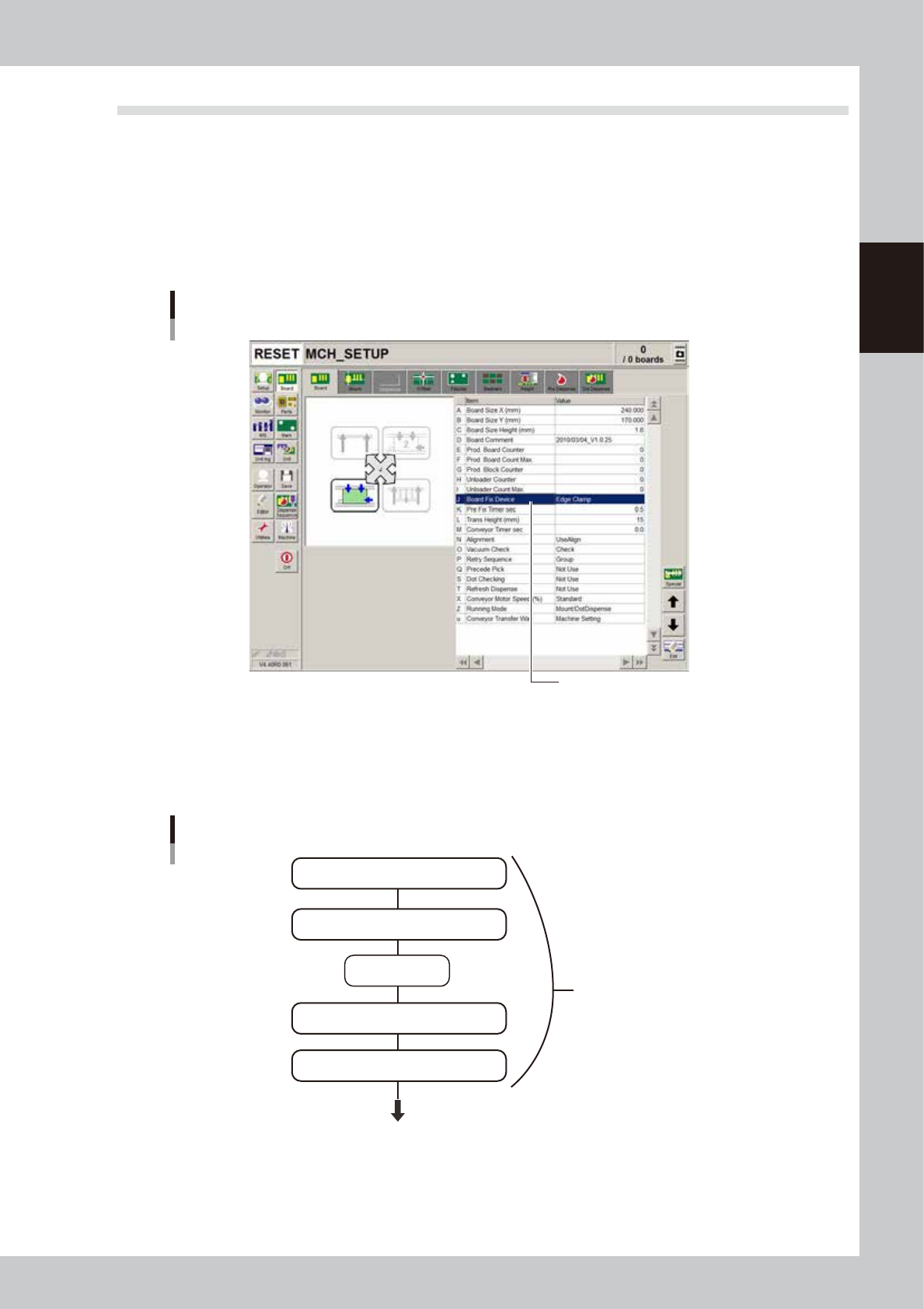
3.3.1 Conveyor unit setup flow
The flow chart below shows the sequence for setting up the conveyor unit. The method for adjusting each
conveyor unit is described in the following sections.
Flow chart for changing the conveyor unit setups
Adjust conveyor width
Press emergency
stop button
Raise main stopper
Adjust board hold plate positoins as needed
Arrange push-up pins on push-up plate
Conveyor unit setups
Next step (head unit setup)
63206-N7-10