cp45电脑部分判断.pdf - 第8页
6. PC Ver. Date CP45 CP45NEO 00 2004/11 O O 6-1 6-2 Indust rial PC Industrial PC : Layout is as Follows Part Li st of Indu stria l PC No. Code Item Spec. 1 J9070051A JOY-606A-INDUSTRIAL CHASSIS J9070051A 2 J4801015A SBC …
6. PC
Ver. Date CP45
CP45NEO
00 2004/11 O O
6-1
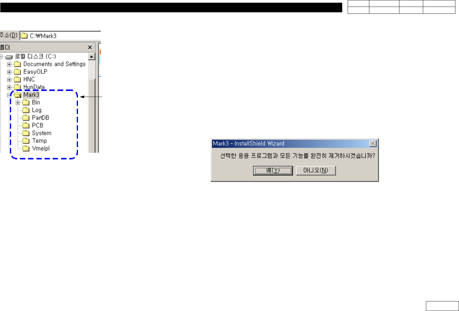
6-1-2-5) Copy System Data from Original File
*InCaseofCreatingNewHDD
: Back Up All C:\Mark3 Folder from Original File(Existing HDD)
InstallNewMMIinHDDandOverwriteMark3FolderofBackUpFileinNewHDD
*InCaseofUpgradingMMI
(1) Back Up Existing Mark3 (for the Case of Original Recovery)
(2) Before Upgrade, Check if There is Change in Constant
If There is no Change, just Checking Constant Value after Installing New Version is
Enough.
But If There is Change, Record the Value of Present Equipment(before Upgrade)
(3) Asked Remove when Selecting Installation, Select Yes
(4) Select Installation Again to Install New Version
(5) When the Installation is Completed, Turn OFF-ON Equipment, Run Mark3 and Home
If Home is Completed, Compare with the Constant Value Recorded before and
Re-input Necessary Part
(6) After MMI Upgrade, Read Component Library with 'Merge Part Library' Function
For Copy, Some Data can be Incompatible by Version Difference
Fig.6-1-2-2 System file copy folder for
HDD exchange
for HDDexchange
6. PC
Ver. Date CP45
CP45NEO
00 2004/11 O O
6-1
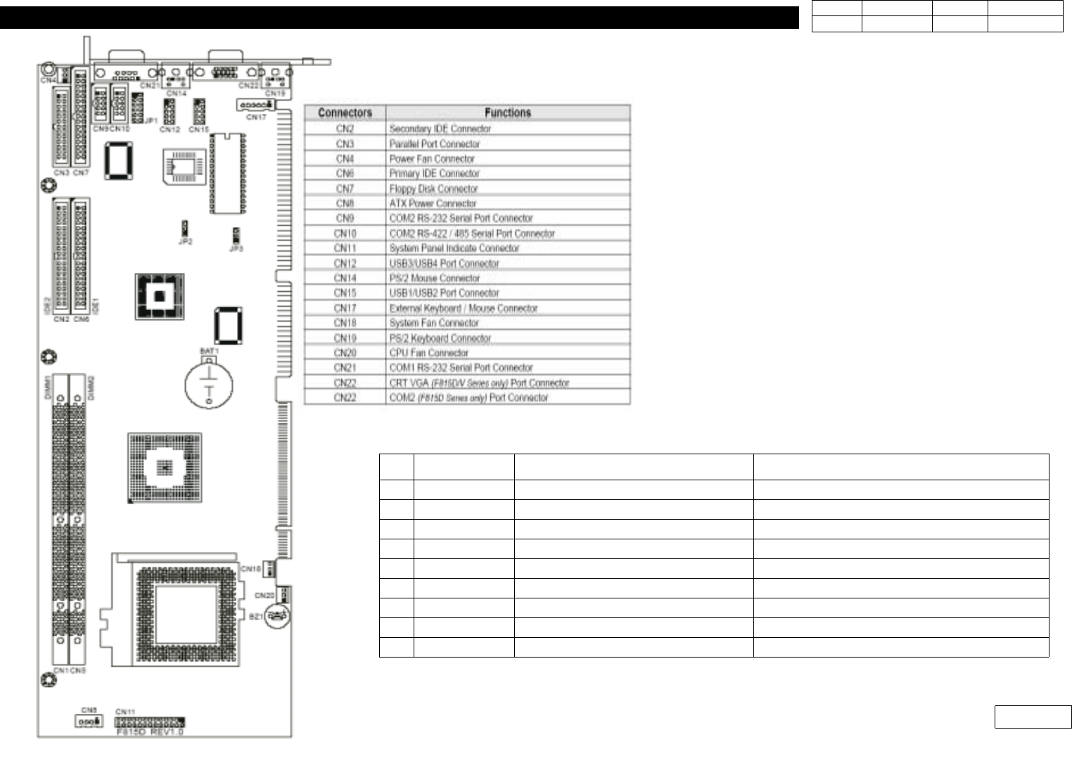
6-2 Industrial PC
Industrial PC : Layout is as Follows
Part List of Industrial PC
No.
Code Item Spec.
1 J9070051A JOY-606A-INDUSTRIAL CHASSIS J9070051A
2 J4801015A SBC (Mothor Board) F815D/V FULL-SIZE SBC
3 J4809047A PCI-6S PCI/ISA BACK PLANE PCI-6S PCI/ISA BACK PLANE
4 J4401032A SWITCHING POWER SUPPLY ATX250-SEV
5 J4901012A CPU INTEL CELERON 1.3GHZ(include FAN)
6 J5101020A HARD DISK DRIVER IC35L060AVV207-0(HITACHI(IBM)3.5
7 J5001008A MODULE RAM SDRAM 128M 168PIN PC133
8 J7070173A PC BRACKET J7070173A(Industrial)
9 J3802003A USB PORT USB 1.0
Fig.6-2 SBC (Industrial PC) Board Layout
6. PC
Ver. Date CP45
CP45NEO
00 2004/11 O O
6-1
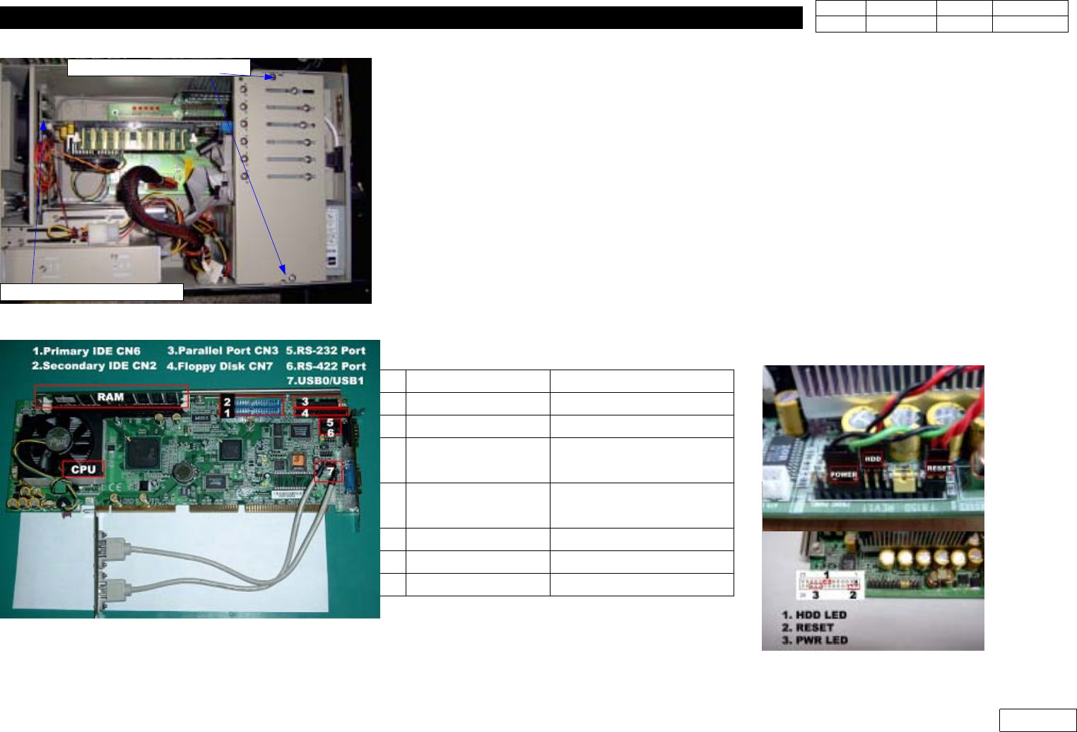
6-2-1 SBC Replacement Procedure
(1) Separate CARD Support inside Industrial PC
(2) Separate Connectors Attached to SBC Board, and Separate SBC Board from Back Plane
At this Time, be Careful not to Damage Pin
(3) Separate CPU(Unity with Fan), Ram from SBC
When Separating CPU, be Careful not to Damage Chip on SBC
(4) Replace SBC, Assemble CPU, RAM and Assemble Connectors to SBC (Ref. Fig. 6-2-2)
(5) Check SBC Jumper (Ref. Fig 6-2-3)
(6) Assemble SBC to Back Plane. Assemble Separated Connector
(Ref. Fig 6-2-2, Table)
(7) Check CMOS Setting (Ref. 6-2-2 CMOS Setting Procedure)
(1) Remove Card Support
(2)Seperator SBC Board
Fig.6-2-2 SBC Board(CPU,RAM,Connectors)
Fig.6-2-1 Seperator SBC Board.
Fig.6-2-3 SBC Jumper Setting
No. Fuction Cabel
1 Primary IDE CN6 HDD
2 Secondary IDE CN2 CD Driver
3 Parallel Port CN3
Pinter Port
(PC01: J9061330A Cable)
4 Floppy Disk CN7
Floppy
(PC05:J9061769A Cable)
5 COM2 RS232 CN9 RS232
6 CON2 RS422 CN10 RS 422
7 USB3/4 CN12 USB Port