00192393-02.pdf - 第38页
Modulare Koplatine an S -23, S-25 HM , F5 HM, HS- 50 Nachrüstanleitung SI PLACE 1.7 Anhang Schalt pläne, Layout (Vision-Bo ard) Ausgabe 02/ 2003 36
Nachrüstanleitung SIPLACE Modulare Koplatine an S-23, S-25 HM, F5 HM, HS-50
Ausgabe 02/2003 1.7 Anhang Schaltpläne, Layout (Vision-Board)
35
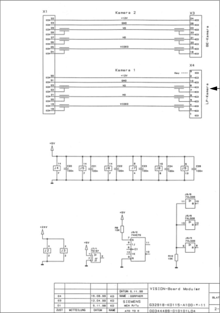
Abb. 1.7.3 Schaltplan Vision-Board modular: Anschluß LP-Kamera (Normallicht) bzw. Multicolor
Unterportal-LP-Kamera (Normallicht)
oder der LP-Kamera Multicolor
Kabel "Kamera" der
Modulare Koplatine an S-23, S-25 HM, F5 HM, HS-50 Nachrüstanleitung SIPLACE
1.7 Anhang Schaltpläne, Layout (Vision-Board) Ausgabe 02/2003
36
Retrofitting Instructions SIPLACE Modular Head PCB on S-23, S-25 HM, F5 HM, HS-50
02/2003 Edition 2.1 Overview
37
5HWURILWWLQJ,QVWUFWLRQV0RGXODU+HDG
3&%RQ66+0)+0+6
2YHUYLHZ
These instructions describe how to retrofit the "Modular head PCB assembly" on SIPLACE F5
HM, S-23, S-25 HM and HS-50 machines. Retrofitting on an F5 HM is not explicitly documented
with photographs, however this is done in much the same manner as for S-23/S-25 HM
machines. Procedural deviations are discussed at the appropriate point during implementation.
Only the Siemens SMD service engineer is permitted to perform the retrofitting.
The modular head PCBs have to be installed under the following conditions:
– When retrofitting the optional PCB camera Multicolor.
(see the retrofitting instructions for the PCB camera Multicolor, Item no. 00192232-01, German
and English). For this reason, the retrofit kit "Modular head PCB" is also included in the PCB
camera retrofit kit for HS-50 and S-23/S-25 HM machines.
– When there is fault in the existing "Conversion PCB, small axis"
The modular PCB boards must always be installed on all gantries.
The PCB unit of the "Head PCB, Assembly" (modular) consists of 4 PCBs:
– Gantry head distributor HS-50 or S-23/S-25 HM or F5 HM (modular)
– Processor board 80 C515C
– SM board, modular
– Vision board, modular
Item numbers: see Section 2.4.1. or Section 2.4.2 or Section 2.4.3.
There is a separate head PCB assembly for F5 HM machines (see Section 2.4.3). The required
ribbon cables are identical to those for the S-25 HM (S-23) however.
7DNHQRWHRI
– To retrofit the modular head boards, relatively old S-23 machines that have been upgraded to
S-25 HM, you require 3 new 10-pin connectors and 1 new 16-pin connector that have to be
fitted on the existing ribbon cables (see Fig. 2.6.4), as described in this isntructions.
This is required to produce the strain relief for the cables.
– The service center stocks the parts and special tools required for this purpose in a separate
service package (detail -> see Section 2.4.4).