00192393-02.pdf - 第51页
Retrofitting Instr uctions SIP LACE Modular Head PCB on S-23, S-25 HM, F5 HM, HS-50 02/2003 Edition 2.5 Preparatory Steps 49 Å P ush the X-gantri es towa rd the outside of the mac hine so that the placeme nt heads ar e r…

Modular Head PCB on S-23, S-25 HM, F5 HM, HS-50 Retrofitting Instructions SIPLACE
2.5 Preparatory Steps 02/2003 Edition
48
3UHSDUDWRU\6WHSV
DANGER
Strictly adhere to the instructions in the DANGER text in Section 2.2.
Take note of the warning symbols at the area of the gantries of HS-50: It is DANGEROUS for any-
one wearing a HEART PACEMAKER to come near the linear motors of an HS-50 machine, as
described in detail in the User Manual and in the Service Manual, in the Capter "Special safety
instructions when working in the vicinity of powerfull magnetic fields".
It is ONLY necessary to undock the movable component changeover tables / the MTC when up-
grading an
S-25 HM machine or when retrofitting the PCB camera Multicolor, so that access to the placement
heads is optimal. In this case, comply with the special safety instructions in the pertinent retrofitting
instructions.
High risk of injury exists from the blades and the tape deflector of the cutter, even when the ma-
chine has been turned off.
Never reach into the pneumatic cutter from below or into the empty-tape duct from above, not
even to resolve a problem (e.g., when tape is jammed before the component changeover table is
undocked).
Å :KHQUHWURILWWLQJWKHPRGXODUKHDG3&%VZKLOHUHWURILWWLQJWKH3&%FDPHUD0XOWLFRORU
FDUU\RXWWKHIROORZLQJVWHSV
Å Perform each step - beginning with those in the "Preparatory Steps" - as described in the
retrofitting instructions for the PCB camera Multicolor.
Å After converting the main distributor (on an HS-50) or the terminal panel, LH and RH (on
S-25 HM), proceed to the steps in Section 2.6.
Å ,I21/<WKHPRGXODUKHDG3&%LVEHLQJUHWURILWWHGFDUU\RXWWKHIROORZLQJVWHSV
Å Turn the machine OFF at the main switch, isolate the machine from the mains, turn OFF
the flow of compressed air at the compressed air unit (see DANGER text in Section 2.2).
Å Open the safety hoods and the safety doors on the area of component feeders.
NOTE:
It is NOT necessary to undock the component changeover tables / the MTC if you are just
installing the head PCBs.
Retrofitting Instructions SIPLACE Modular Head PCB on S-23, S-25 HM, F5 HM, HS-50
02/2003 Edition 2.5 Preparatory Steps
49
Å Push the X-gantries toward the outside of the machine so that the placement heads are
readily accessible.
Å On the placement heads loosen screws fastening the cover in questions (5 screws for each)
and take off the covers
Refer to the NOTE in Section 2.1 regarding the continued use of the covers.
Modular Head PCB on S-23, S-25 HM, F5 HM, HS-50 Retrofitting Instructions SIPLACE
2.6 Installing the Head PCB, Modular 02/2003 Edition
50
,QVWDOOLQJWKH+HDG3&%0RGXODU
CAUTION
Comply with the ESD regulations while handling the PCBs as described below.
Use the ESD bracelet and connect it to the grounding button on the machine that is provided for
this purpose.
Make certain that NO screws or other parts drop into the machine or the placement head.
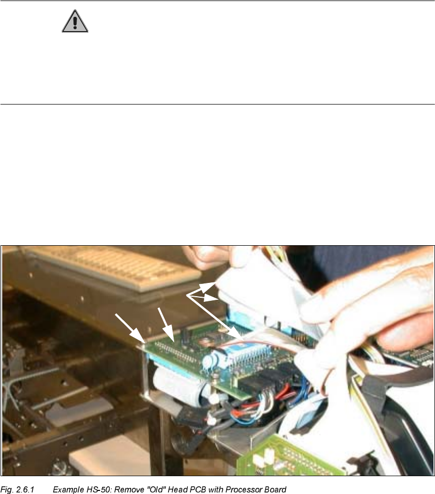
5HPRYLQJ2OG+HDG3&%ZLWK3URFHVVRU%RDUG&RQYHUVLRQ3&%6PDOO
$[LV
The major difference during disassembly is the type of fasteners used for the PCBs:
Screws are used for the HS-50 (see Fig. 2.6.1) and spacer bolts for the S-25, F5HM and F5 HM,
in a like manner to that shown in Fig. 2.6.3. In addition, there is no head cover on the HS-50 as yet.
.H\
1. "old" Head PCB with processor board HS-50 (Conversion PCB, small axis" see Fig. 2.6.2)
2. Fasteners: 4 socket hex head cap screws M3 on the spacer bolts
3. Ribbon cables (are removed completely and replaced by cables from the retrofit kit)