00192393-02.pdf - 第53页
Retrofitting Instr uctions SIP LACE Modular Head PCB on S-23, S-25 HM, F5 HM, HS-50 02/2003 Edition 2.6 Installing the Head PCB, Modular 51 .H\ 1. 4 spacer b olts remov ed (fast ening o f the PC B unit), size 5.5 mm ope…
Modular Head PCB on S-23, S-25 HM, F5 HM, HS-50 Retrofitting Instructions SIPLACE
2.6 Installing the Head PCB, Modular 02/2003 Edition
50
,QVWDOOLQJWKH+HDG3&%0RGXODU
CAUTION
Comply with the ESD regulations while handling the PCBs as described below.
Use the ESD bracelet and connect it to the grounding button on the machine that is provided for
this purpose.
Make certain that NO screws or other parts drop into the machine or the placement head.
5HPRYLQJ2OG+HDG3&%ZLWK3URFHVVRU%RDUG&RQYHUVLRQ3&%6PDOO
$[LV
The major difference during disassembly is the type of fasteners used for the PCBs:
Screws are used for the HS-50 (see Fig. 2.6.1) and spacer bolts for the S-25, F5HM and F5 HM,
in a like manner to that shown in Fig. 2.6.3. In addition, there is no head cover on the HS-50 as yet.
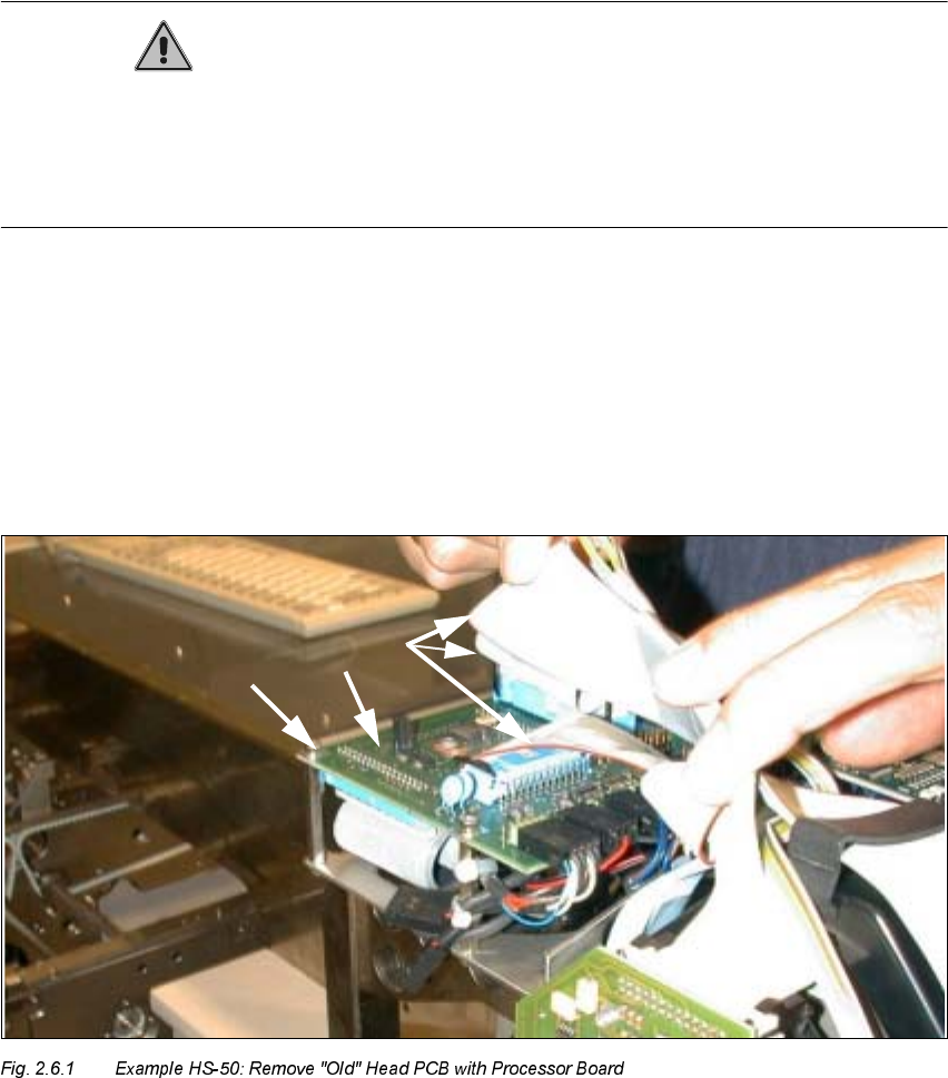
.H\
1. "old" Head PCB with processor board HS-50 (Conversion PCB, small axis" see Fig. 2.6.2)
2. Fasteners: 4 socket hex head cap screws M3 on the spacer bolts
3. Ribbon cables (are removed completely and replaced by cables from the retrofit kit)
Retrofitting Instructions SIPLACE Modular Head PCB on S-23, S-25 HM, F5 HM, HS-50
02/2003 Edition 2.6 Installing the Head PCB, Modular
51
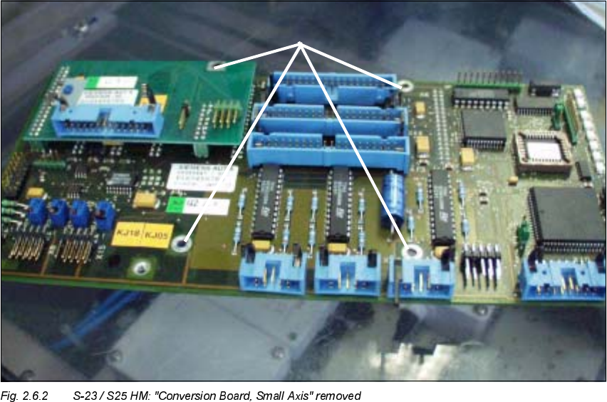
.H\
1. 4 spacer bolts removed (fastening of the PCB unit), size 5.5 mm open-end wrench
Å Wear the ESD bracelet (see CAUTION text above).
Å CAREFULLY detach all connectors on the top of the "Conversion PCB, small axis" / on the
"old" Head PCB with processor board (on all placement heads).
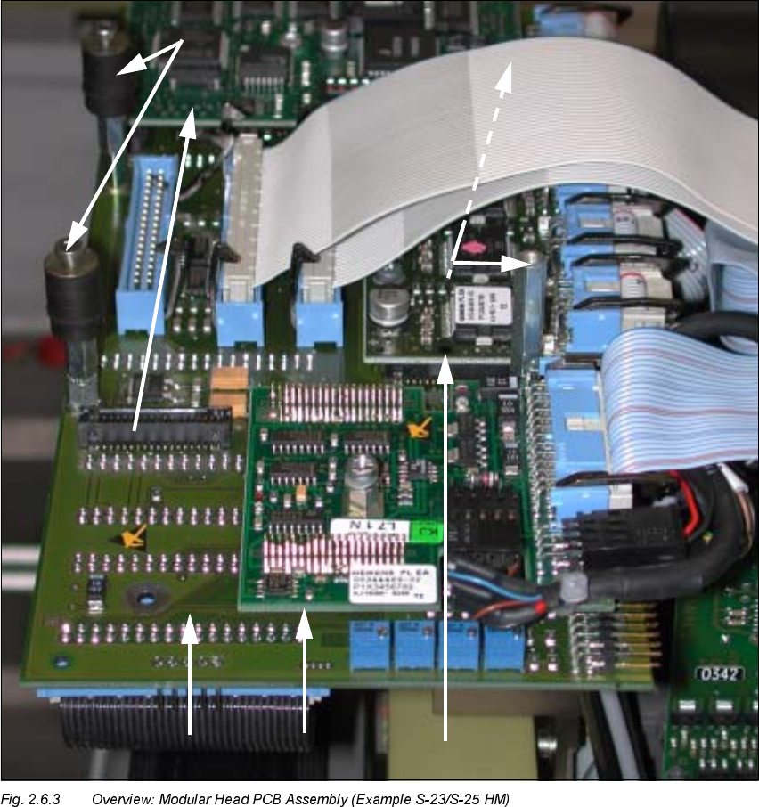
Å In each case, remove the two wide and the narrower ribbon cable (see Fig. 2.6.1 -> 3) from the
placement head because they are being replaced by the new cables in the retrofit kit.
Å Set the remaining cables to one side such that there is no contact between them.
– For the S-23, S-25 HM, F5 HM:
4 spacer bolts on the "Conversion PCB, small axis" (see Fig. 2.6.2 / in like manner to that
shown in Fig. 2.6.3)
– For the HS-50:
4 socket hex head cap screws on the "old" head PCB with processor boards (see Fig.
2.6.1).
Å Lift the PCB slightly and unplug the 4 ribbon cable connectors on the bottom of the PCB.
Å Remove the PCB and place it in an antistatic package immediately.
Modular Head PCB on S-23, S-25 HM, F5 HM, HS-50 Retrofitting Instructions SIPLACE
2.6 Installing the Head PCB, Modular 02/2003 Edition
52
,QVWDOOLQJWKH+HDG3&%0RGXODU
Å
Continue to wear the ESD bracelet (see CAUTION text above).
Å Pick up the pertinent new modular head PCB assembly:
(Item no.: see Section 2.4.1, Section 2.4.2 or Section 2.4.3).
.H\
1. Gantry head distributor, modular, basic board
2. Processor board 80 C515C