00192393-02.pdf - 第56页
Modular Head P CB on S -23, S-25 HM, F5 HM, HS- 50 Retrofitting Instructions SIPLACE 2.6 Installing the Head PCB, Modular 02/2003 Edition 54 8S JUDGH G 2OG HU 6 6 +0 0DFKL QHV 21/ < ,QVWDOOLQJ…
Retrofitting Instructions SIPLACE Modular Head PCB on S-23, S-25 HM, F5 HM, HS-50
02/2003 Edition 2.6 Installing the Head PCB, Modular
53
.H\WR)LJFRQWLQXHG
3. SM-Board modular
4. Vision-Board modular
5. Spacer bolts with rubber buffer to fasten the head cover (open-end wrench, size 5.5 mm) *)
6. Spacer bolts to support the head cover (open-end wrench, size 5.5 mm) *)
*) and to fasten the head PCB assembly to the 4 spacer bolts on the head support
Å Comply with the ESD regulations. Use ESD tools and the ESD bracelet.
Å On each of the Placement head make the connections of the 4 ribbon cables on the bottom of
the "Gantry head distributor board" again.
Å Carefully place the new PCB assembly on the existing spacer bolts.
Å For the HS-50:
Re-use the 4 socket hex head cap screws M3 (size 2.5 mm) removed during disassembly to
fasten the PCB assembly to the 4 spacer bolts of the head support.
Å For the S-23, S-25 HM, F5 HM:
Use the 4 spacer bolts that were removed while working from the top of the PCB during the
disassembly of the "Conversion board, small axis".
With these 4 spacer bolts (open-end wrench size 5.5 mm) fasten the new PCB assembly on
the spacer bolts of the head support.
Refer to Fig. 2.6.3 to see how the spacer bolts are arranged:
- 2 spacer bolts that the head cover (Pos. no. 6) will rest on and
- 2 spacer bolts with rubber vibration dampers to fasten the head cover (Pos. no. 5).
Å The next step in the case of older S-23 or S-25 HM machines that have been upgraded from
older S-23 machines is to check whether the strain relief devices on the connectors of the new
PCBs still match the jack connectors on the existing ribbon cables.
To do so, proceed as described in Section 2.6.3.
Å The next step is to check the PIN allocation (see Section 2.6.4).
Modular Head PCB on S-23, S-25 HM, F5 HM, HS-50 Retrofitting Instructions SIPLACE
2.6 Installing the Head PCB, Modular 02/2003 Edition
54
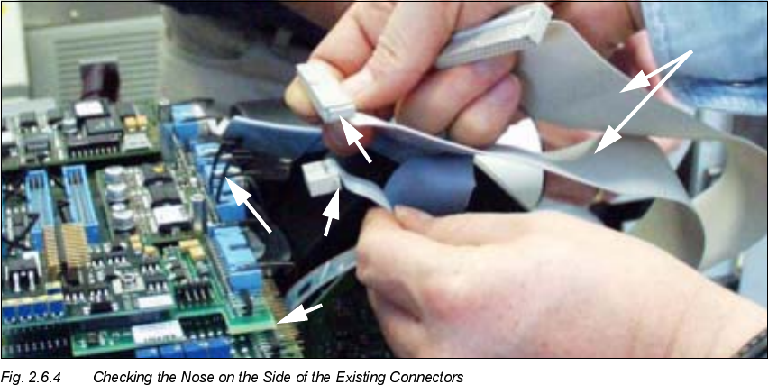
8SJUDGHG2OGHU66+00DFKLQHV21/<,QVWDOOLQJ1HZ&RQQHFWRUV
Å
Check whether the strain relief devices for the new PCB assembly still fit, as shown below in
Fig. 2.6.4 and Fig. 2.6.5:
– on the 3 ribbon cables of the adjustment units (SLQconnectors) and
– on the 16-pin ribbon cable for vacuum (SLQconnectors)
.H\
1. Modular head PCB, complete, installed
2. Strain relief device on PCB connectors
3. NEW connector = large nose on the entire side = matching
4. OLD connector = small nose connector must be exchanged.
5. 2 ribbon cables, 40-pin, and 1 ribbon cable, 26-pin *)
*) These cables are always exchanged on HS-50 and on S-23, S-25 HM and F5 HM because the
cable run has been changed (see Fig. 2.6.7 to Fig. 2.6.11).
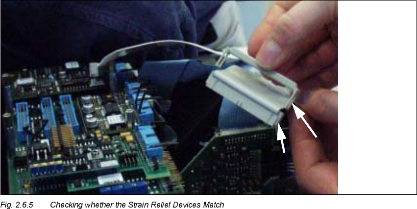
Retrofitting Instructions SIPLACE Modular Head PCB on S-23, S-25 HM, F5 HM, HS-50
02/2003 Edition 2.6 Installing the Head PCB, Modular
55
.H\WR)LJ
1. Strain relief device, suitable for the connectors of the modular head PCB
2. Big nose on the connector
Å If the strain relief devices on the 10-pin and 16-pin ribbon cable connectors match, proceed to
the next section.
Å If the strain relief bars do NOT match, mount the new connectors and strain relief devices from
the separate service package (see Section 2.4.4) as follows:
Å With an indelible marker, mark PIN 1 on each of the DERYHPHQWLRQHG4 ribbon cables.
Å Use the ribbon cable pliers from the separate service package to remove the DERYHPHQ
WLRQHG4 ribbon cable connectors as close as possible behind the connector.
Å Use the crimping tool for ribbon cable and the new connectors from the separate service
package:
- For each placement head: 3 units 10-pin insulation displacement connectors made
by Bancon, Order no. 050-010-435 A
- For each placement head: 1 unit 16-pin insulation displacement connector made by
Bancon, Order no. 050-016-435 A
Å Attach these connectors to the ribbon cables in the correct rotational position/PIN alloca-
tion.