00192393-02.pdf - 第57页
Retrofitting Instr uctions SIP LACE Modular Head PCB on S-23, S-25 HM, F5 HM, HS-50 02/2003 Edition 2.6 Installing the Head PCB, Modular 55 .H\W R )LJ 1. S t rain relief d evice, sui table for the connec t…
Modular Head PCB on S-23, S-25 HM, F5 HM, HS-50 Retrofitting Instructions SIPLACE
2.6 Installing the Head PCB, Modular 02/2003 Edition
54
8SJUDGHG2OGHU66+00DFKLQHV21/<,QVWDOOLQJ1HZ&RQQHFWRUV
Å
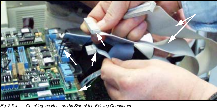
Check whether the strain relief devices for the new PCB assembly still fit, as shown below in
Fig. 2.6.4 and Fig. 2.6.5:
– on the 3 ribbon cables of the adjustment units (SLQconnectors) and
– on the 16-pin ribbon cable for vacuum (SLQconnectors)
.H\
1. Modular head PCB, complete, installed
2. Strain relief device on PCB connectors
3. NEW connector = large nose on the entire side = matching
4. OLD connector = small nose connector must be exchanged.
5. 2 ribbon cables, 40-pin, and 1 ribbon cable, 26-pin *)
*) These cables are always exchanged on HS-50 and on S-23, S-25 HM and F5 HM because the
cable run has been changed (see Fig. 2.6.7 to Fig. 2.6.11).
Retrofitting Instructions SIPLACE Modular Head PCB on S-23, S-25 HM, F5 HM, HS-50
02/2003 Edition 2.6 Installing the Head PCB, Modular
55
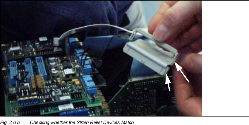
.H\WR)LJ
1. Strain relief device, suitable for the connectors of the modular head PCB
2. Big nose on the connector
Å If the strain relief devices on the 10-pin and 16-pin ribbon cable connectors match, proceed to
the next section.
Å If the strain relief bars do NOT match, mount the new connectors and strain relief devices from
the separate service package (see Section 2.4.4) as follows:
Å With an indelible marker, mark PIN 1 on each of the DERYHPHQWLRQHG4 ribbon cables.
Å Use the ribbon cable pliers from the separate service package to remove the DERYHPHQ
WLRQHG4 ribbon cable connectors as close as possible behind the connector.
Å Use the crimping tool for ribbon cable and the new connectors from the separate service
package:
- For each placement head: 3 units 10-pin insulation displacement connectors made
by Bancon, Order no. 050-010-435 A
- For each placement head: 1 unit 16-pin insulation displacement connector made by
Bancon, Order no. 050-016-435 A
Å Attach these connectors to the ribbon cables in the correct rotational position/PIN alloca-
tion.
Modular Head PCB on S-23, S-25 HM, F5 HM, HS-50 Retrofitting Instructions SIPLACE
2.6 Installing the Head PCB, Modular 02/2003 Edition
56
Å Mount the strain relief device (see separate service package) on the connectors:
- for 10-pin connector, Order no. 050-000-010
- for 16-pin connector, Order no. 050-000-016
Å As the next step, check the PIN allocation.
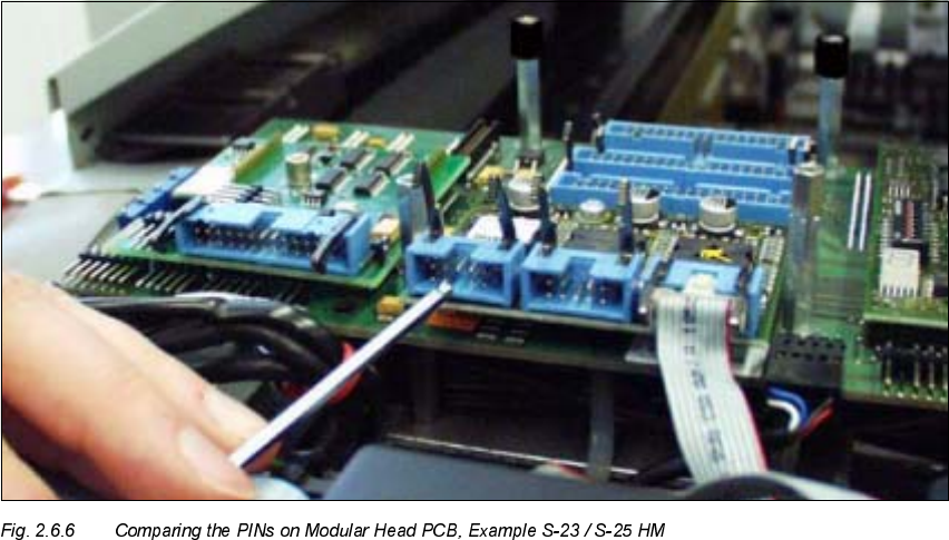
&KHFNLQJWKH&RQQHFWRU$OORFDWLRQ5HPRYHG3,16RI0RGXODU+HDG3&%V
Å To be on the safe side, check the PINs of the connectors of all modular head PCBs
(S-23/S-25HM, F5 HM, HS-50) by comparing each with the jack connector to be connected to
it.
-> Upon receipt, the pertinent PINs must have already been removed.
In the exceptional case that this is not the case, remove with pertinent PIN with the ESD ob-
lique-nosed cutting pliers.
Å Proceed to lay the cables and to plug in the connectors, as described in Section 2.6.5.