00192393-02.pdf - 第59页
Retrofitting Instr uctions SIP LACE Modular Head PCB on S-23, S-25 HM, F5 HM, HS-50 02/2003 Edition 2.6 Installing the Head PCB, Modular 57 0DNHWKH&RUUHF W&DEOH5XQDQG3O XJ,Q&RQQHFWLRQV NOTE: Lay…
Modular Head PCB on S-23, S-25 HM, F5 HM, HS-50 Retrofitting Instructions SIPLACE
2.6 Installing the Head PCB, Modular 02/2003 Edition
56
Å Mount the strain relief device (see separate service package) on the connectors:
- for 10-pin connector, Order no. 050-000-010
- for 16-pin connector, Order no. 050-000-016
Å As the next step, check the PIN allocation.
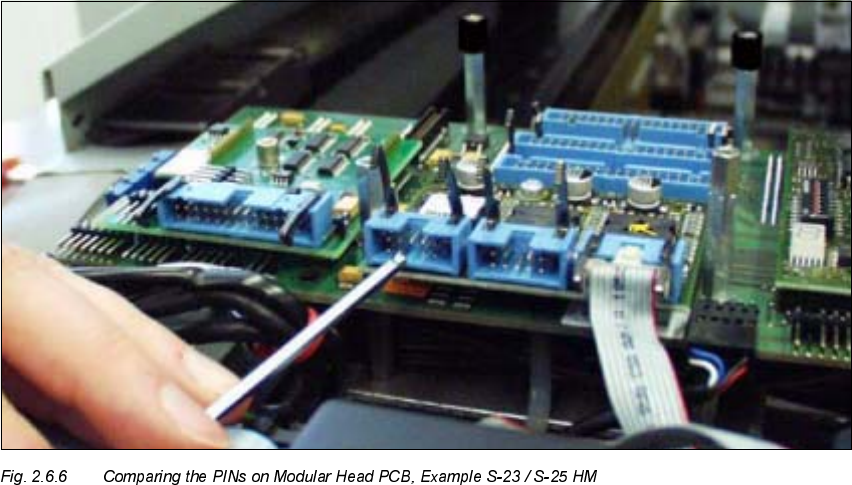
&KHFNLQJWKH&RQQHFWRU$OORFDWLRQ5HPRYHG3,16RI0RGXODU+HDG3&%V
Å To be on the safe side, check the PINs of the connectors of all modular head PCBs
(S-23/S-25HM, F5 HM, HS-50) by comparing each with the jack connector to be connected to
it.
-> Upon receipt, the pertinent PINs must have already been removed.
In the exceptional case that this is not the case, remove with pertinent PIN with the ESD ob-
lique-nosed cutting pliers.
Å Proceed to lay the cables and to plug in the connectors, as described in Section 2.6.5.
Retrofitting Instructions SIPLACE Modular Head PCB on S-23, S-25 HM, F5 HM, HS-50
02/2003 Edition 2.6 Installing the Head PCB, Modular
57
0DNHWKH&RUUHFW&DEOH5XQDQG3OXJ,Q&RQQHFWLRQV
NOTE:
Laying the cables correctly is a prerequisite for proper assemble of the head cover (see NOTE in
Section 2.1). In the following figures you see the modular Head PCB assembly with the PCB
board, modular (installed only when retrofitting the "PCB camera Multicolor" at the same time).
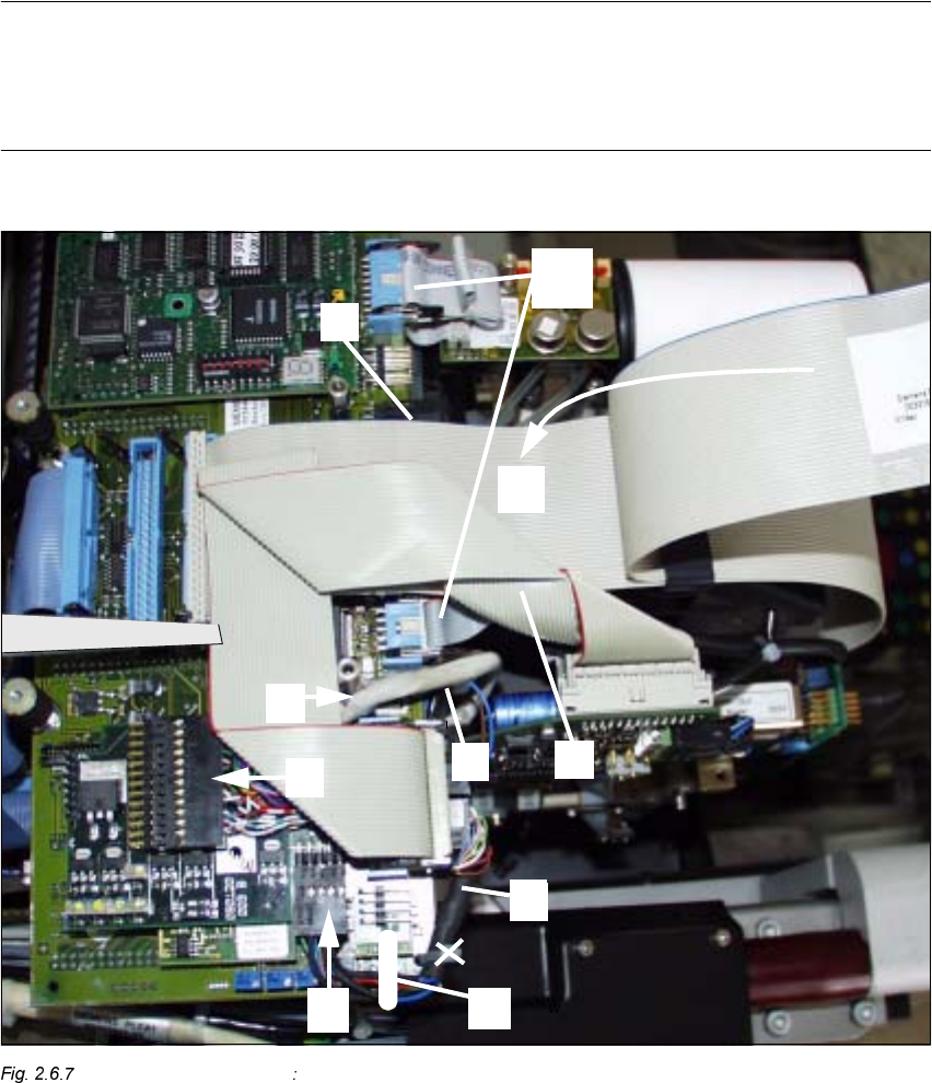
S-23/S-25 HM (F5 HM) 1st Step while Laying Cable in the Area of the Head PCB
.H\WR)LJ
1. Cable "Illumination" (PCB camera Multicolor)
2. Cable "Illumination" (Multicolor) -> plug-in connection X3 (PCB camera board, modular)
(NOTE: Cable "Illumination" of PCB camera with normal illumination on X -> see Fig. 2.7.2)
Modular Head PCB on S-23, S-25 HM, F5 HM, HS-50 Retrofitting Instructions SIPLACE
2.6 Installing the Head PCB, Modular 02/2003 Edition
58
&RQWLQXDWLRQ.H\WR)LJ
3. Cable "Camera" (PCB camera: Multicolor or normal illumination)
4. Cable "Camera" (Multicolor or normal illumination) -> plug-in connection X4 (Vision board,
modular)
5. Cable tie: fastening of cable "Camera"
in the hole of the Vision board, modular *)
6. Ribbon cable lying at bottom, new, contained at Item no 00358917-01
(= mount when retrofitting the modular head PCB)
7. Preshaped ribbon cable, new, Item no. 00351063-01
(= mount when retrofitting the modular head PCB)
8. Ribbon cable lying at top, contained at Item no. 00358917-01
(= mount when retrofitting the modular head PCB)
9. Cable tie: fastening the cable "Illumination" of PCB camera Multicolor
10.3 ribbon cables, 10-pin (units for positioning, e.g. turning station) and 1 ribbon cable, 16-pin
(vacuum).
Take note of:
If the strain relief device of the modular head PCB does not fit on the S-25 HM machine, you
have to mount new connectors on the ribbon cables (see Section 2.6.3)!
-> all plug-in connections on the Vision board, modular -> see Figures in Section 2.7
<RXZLOOILQGWKHXSGDWHGUHSUHVHQWDWLRQRIWKHIDVWHQLQJRIWKLVFDEOHLQWKHIROORZLQJ
)LJ