00192393-02.pdf - 第61页
Retrofitting Instr uctions SIP LACE Modular Head PCB on S-23, S-25 HM, F5 HM, HS-50 02/2003 Edition 2.6 Installing the Head PCB, Modular 59 HS-50/S-23/S-25 HM/F5 HM Å Us e the Fig ures in Sect ion 2.7 for the al locatio …
Modular Head PCB on S-23, S-25 HM, F5 HM, HS-50 Retrofitting Instructions SIPLACE
2.6 Installing the Head PCB, Modular 02/2003 Edition
58
&RQWLQXDWLRQ.H\WR)LJ
3. Cable "Camera" (PCB camera: Multicolor or normal illumination)
4. Cable "Camera" (Multicolor or normal illumination) -> plug-in connection X4 (Vision board,
modular)
5. Cable tie: fastening of cable "Camera"
in the hole of the Vision board, modular *)
6. Ribbon cable lying at bottom, new, contained at Item no 00358917-01
(= mount when retrofitting the modular head PCB)
7. Preshaped ribbon cable, new, Item no. 00351063-01
(= mount when retrofitting the modular head PCB)
8. Ribbon cable lying at top, contained at Item no. 00358917-01
(= mount when retrofitting the modular head PCB)
9. Cable tie: fastening the cable "Illumination" of PCB camera Multicolor
10.3 ribbon cables, 10-pin (units for positioning, e.g. turning station) and 1 ribbon cable, 16-pin
(vacuum).
Take note of:
If the strain relief device of the modular head PCB does not fit on the S-25 HM machine, you
have to mount new connectors on the ribbon cables (see Section 2.6.3)!
-> all plug-in connections on the Vision board, modular -> see Figures in Section 2.7
<RXZLOOILQGWKHXSGDWHGUHSUHVHQWDWLRQRIWKHIDVWHQLQJRIWKLVFDEOHLQWKHIROORZLQJ
)LJ
Retrofitting Instructions SIPLACE Modular Head PCB on S-23, S-25 HM, F5 HM, HS-50
02/2003 Edition 2.6 Installing the Head PCB, Modular
59
HS-50/S-23/S-25 HM/F5 HM
Å Use the Figures in Section 2.7 for the allocation of the connectors on the Vision Board.
Å ,QFDVHRI3&%FDPHUDZLWKQRUPDOLOOXPLQDWLRQDQGSRVVLEOHRSWLRQREOLTXHLOOXPLQD
WLRQ
Å Run the pertinent cable "Camera" and "illumination" in the area of the head PCB strictly as
shown in the following illustrations and appropriately adjust the cable guideway for oblique
illumination (not explicitly defined).
- for S-25 HM, S-23, F5 HM -> in Fig. 2.6.7 -> Pos. no. 3 and 1,
- for HS-50 -> in Fig. 2.6.10 -> Pos. no. 3 and 1.
Å Connect the following cables to the pertinent 9LVLRQERDUGPRGXODU:
- cable "Component camera" to X3.
- cable "Camera" of the PCB camera with normal illumination to X4,
- where available, optional oblique illumination to X5,
- cable "illumination" (normal illumination) to plug-in connection X (= PCB illumina-
tion, old)
(= in this case there is a difference compared to the cable "illumination" of the PCB
camera Multicolor)

Modular Head PCB on S-23, S-25 HM, F5 HM, HS-50 Retrofitting Instructions SIPLACE
2.6 Installing the Head PCB, Modular 02/2003 Edition
60
Å ,QFDVHRILQVWDOOHG3&%FDPHUD0XOWLFRORU
Å Run the pertinent cable "Camera" and "illumination" of the PCB camera Multicolor in the
vicinity of the head PCB as shown in the following illustrations:
- for S-25 HM, S-23, F5 HM -> in Fig. 2.6.7 -> Pos. no. 3 and 1,
- for HS-50 -> in Fig. 2.6.10 -> Pos. no. 3 and 1.
NOTE:
All of the cable run for the PCB camera Modular is described in the retrofitting instructions for
Multicolor.
Å Connect the following cables to the pertinent Vision board, modular, and to the PCB board,
modular:
- Cable "Component camera" to X3 on the Vision board, modular,
- Cable "Camera" of the PCB camera Multicolor to X4
- Cable "illumination" of the PCB camera Multicolor to Xof the3&%ERDUGPRGXODU
(= in contrast illumination cable of the PCB camera with normal illumination)
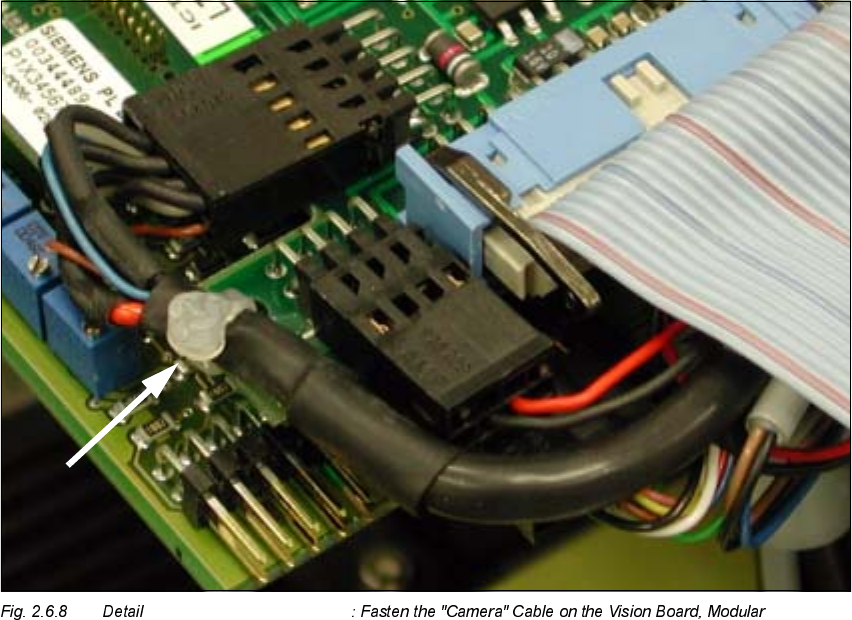
Å Use cable ties to fasten each of the cables "Camera" in the hole of the "Vision board, modular",
as shown in the detail Fig. 2.6.8.
Å Plug in the 3 small ribbon cable connectors of the adjustment units and all of the remaining
connectors.
Å 8VHWKHQHZULEERQFDEOHVIURPWKHSHUWLQHQWUHWURILWNLWVHH6HFWLRQDQG6HFWLRQ
Å The ribbon cables for S-23, S-25 HM and F5 HM are identical.
Å Run the ribbon cables in 6WHSVDQGand plug in the pertinent connectors as shown in
the following illustrations:
- for S-25HM, S-23, F5 HM -> in Fig. 2.6.7 and Fig. 2.6.9 and
- for HS-50 -> in Fig. 2.6.10 and Fig. 2.6.11.
Å :KLOHGRLQJVRQRWHLQWKHGHWDLOIRU)+066+0
Å During the 1st step, run the bottom-most, broad ribbon cable.
Note the allocation "top/bottom" relative to the connector (see Fig. 2.6.7).
Å Fold the repeatedly "folded" (preshaped), narrower ribbon cable down so that it is IODWon
the broad cable: see Fig. 2.6.7 -> 7.