00192393-02.pdf - 第64页
Modular Head P CB on S -23, S-25 HM, F5 HM, HS- 50 Retrofitting Instructions SIPLACE 2.6 Installing the Head PCB, Modular 02/2003 Edition 62 1st Step while Laying Cable in the Are a of the He ad PCB .H\ 1. Cable "…
Retrofitting Instructions SIPLACE Modular Head PCB on S-23, S-25 HM, F5 HM, HS-50
02/2003 Edition 2.6 Installing the Head PCB, Modular
61
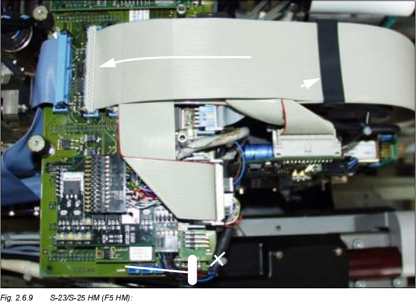
Å During the 2nd step, fold the top-most, wide ribbon cable down and plug the cable onto the
PCB (see Fig. 2.6.9 -> 1).
Å On F5 HM make the plug-in connections of the Pick & Place head on the PCB again.
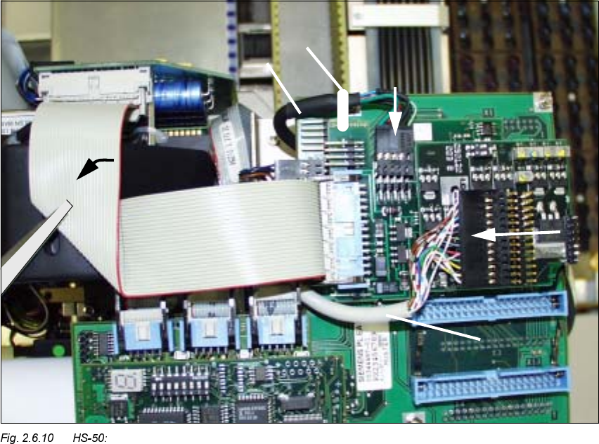
Å :KLOHGRLQJVRQRWHLQWKHGHWDLOIRU+6
Å Run the narrower, new ribbon cable first (see Fig. 2.6.10).
Å Fold it down so that it is flat and in contact
Å Run the two new, wide ribbon cables over it (see Fig. 2.6.11).
Å In conclusion, on all PCBs push the ribbon cable fixing clips into the position shown in each
case (see Fig. 2.6.9 -> 2 or Fig. 2.6.11 -> 2).
Å 0DNHFHUWDLQWKDWDOOFRQQHFWRUVDUHSOXJJHGLQVHFXUHO\
2nd Step while Laying Cable in the Area of the Head PCB
.H\
1. Package of ribbon cables, after running completed and cables connected (F5 HM analogous)
2. Position of the ribbon cable clips
3. Detail of the updated representation of fastening the cable "Camera" -> see Fig. 2.6.8.
Modular Head PCB on S-23, S-25 HM, F5 HM, HS-50 Retrofitting Instructions SIPLACE
2.6 Installing the Head PCB, Modular 02/2003 Edition
62
1st Step while Laying Cable in the Area of the Head PCB
.H\
1. Cable "Illumination" (PCB Camera Multicolor)
2. Cable "Illumination" (Multicolor) -> Plug-in connector X3 (PCB camera board, modular)
(NOTE: Cable "Illumination" of PCB camera with normal illumination on X -> see Fig. 2.7.2)
3. Cable "Camera" (LP-Kamera: Multicolor or normal illumination)
4. Cable "Camera" (Multicolor or normal illumination) -> Plug-in connector X4 (PCB camera
board, modular))
5. Cable tie: To fasten the cable "Camera" on the Vision board, modular *)
6. Preshaped ribbon cable, 1x folded, Item no. 00351523-01
(= new cable, contained in the retrofit kit "head PCB HS-50, modular")
-> all plug-in connections on the Vision board, modular -> see Figures in Section 2.7
5HIHUWR)LJIRUWKHFXUUHQWUHSUHVHQWDWLRQRIIDVWHQLQJWKHFDEOH&DPHUD
Retrofitting Instructions SIPLACE Modular Head PCB on S-23, S-25 HM, F5 HM, HS-50
02/2003 Edition 2.6 Installing the Head PCB, Modular
63
NOTE:
Laying the cables correctly is a prerequisite for proper assemble of the (later available) head cover
Fasten the cable with the cable tie on the Vision board, modular (see Fig. 2.6.8).
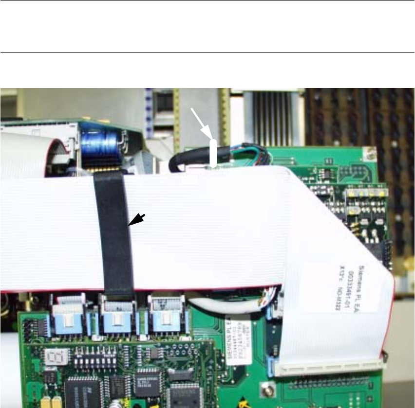
Fig. 2.6.11 HS-50: 2nd Step while Laying Cable in the Area of the Head PCB
.H\
1. 2 ribbon cable: Item no. 00351523-01
(= new cables contained in the retrofit kit "Head PCB HS-50, modular"),
Ribbon cables after running is completed and cables connected.
2. Position of the ribbon cable clips
3. Detail of the updated representation of fastening the cable "Camera" -> see Fig. 2.6.8.