00192393-02.pdf - 第66页
Modular Head P CB on S -23, S-25 HM, F5 HM, HS- 50 Retrofitting Instructions SIPLACE 2.6 Installing the Head PCB, Modular 02/2003 Edition 64 1HZ -XPSHU6HWWLQJRQWKH1HZ 3URFHVVRU%RDUG Set the DIP switch o n t…
Retrofitting Instructions SIPLACE Modular Head PCB on S-23, S-25 HM, F5 HM, HS-50
02/2003 Edition 2.6 Installing the Head PCB, Modular
63
NOTE:
Laying the cables correctly is a prerequisite for proper assemble of the (later available) head cover
Fasten the cable with the cable tie on the Vision board, modular (see Fig. 2.6.8).
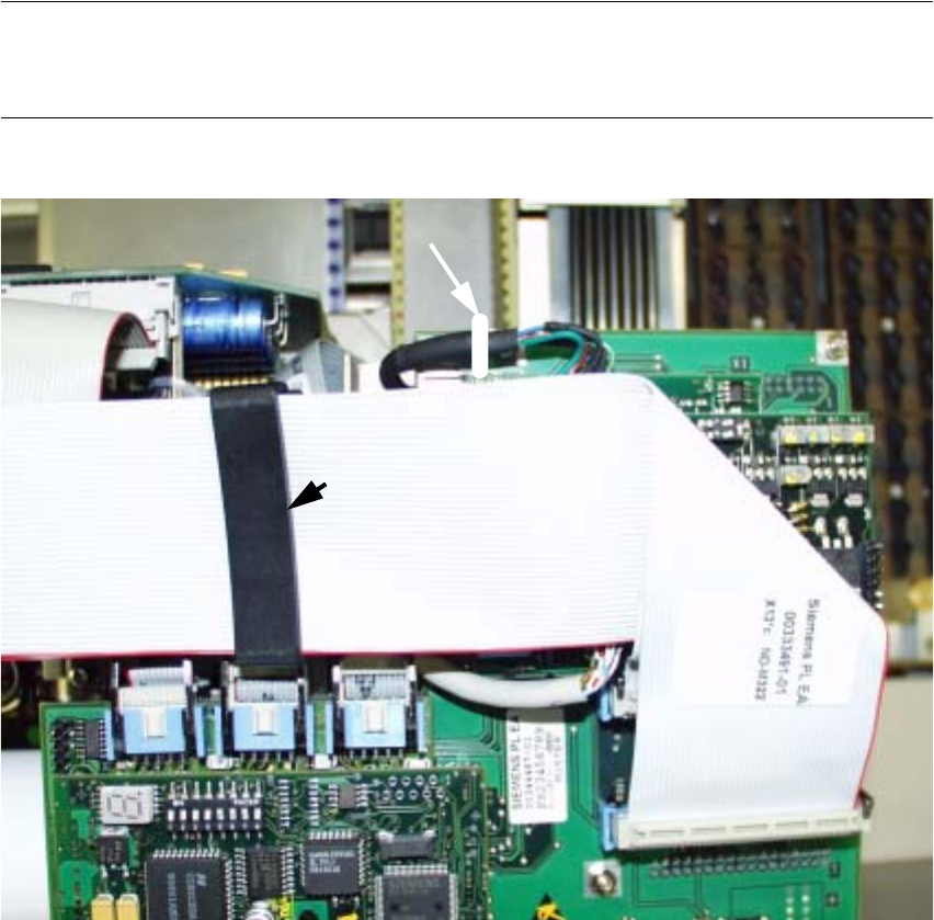
Fig. 2.6.11 HS-50: 2nd Step while Laying Cable in the Area of the Head PCB
.H\
1. 2 ribbon cable: Item no. 00351523-01
(= new cables contained in the retrofit kit "Head PCB HS-50, modular"),
Ribbon cables after running is completed and cables connected.
2. Position of the ribbon cable clips
3. Detail of the updated representation of fastening the cable "Camera" -> see Fig. 2.6.8.
Modular Head PCB on S-23, S-25 HM, F5 HM, HS-50 Retrofitting Instructions SIPLACE
2.6 Installing the Head PCB, Modular 02/2003 Edition
64
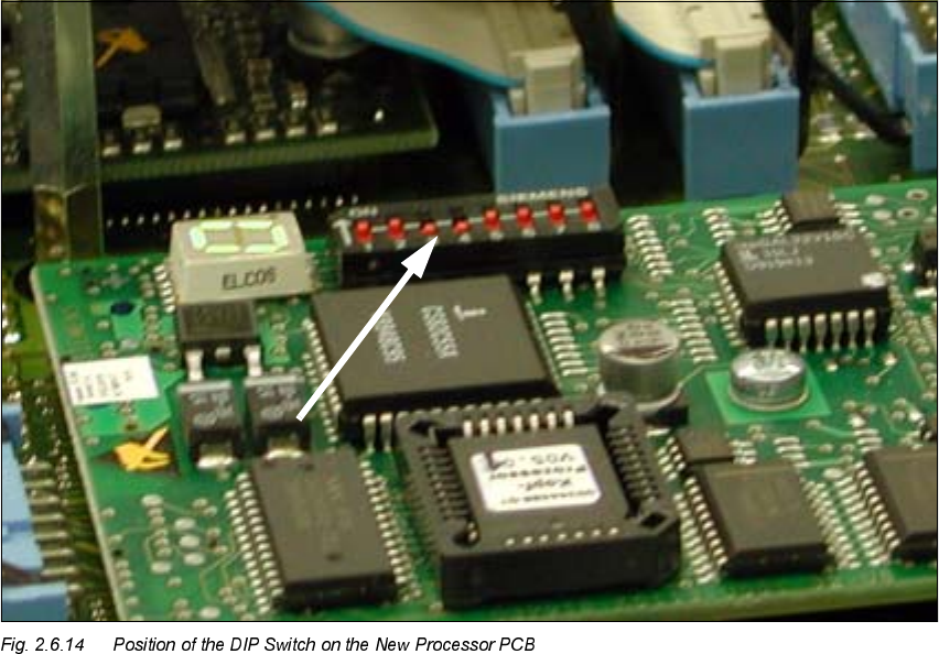
1HZ-XPSHU6HWWLQJRQWKH1HZ3URFHVVRU%RDUG
Set the DIP switch on the processor board on the basis of the following data.
You will see the position of the switch in Fig. 2.6.14, below.
7KHZLULQJRIWKHVZLWFKGHSHQGVRQWKHSODFHPHQWPDFKLQHLQYROYHG
Jumper 1: ON -> CAN matching resistor on the placement head is set
(S-20, F4, F5), S-23, 6+0, F5 HM.
OFF ->CAN_matching resistor is not wired on the head (+6 default)
Jumper 2: ON -> Setting during the download
OFF -> Default status
Jumper 3: ON -> Test mode
OFF -> Default status
Jumper 4: ON -> Test mode (setting of CAN ID)
OFF -> Default status
Jumper 5: ON -> Default status
Jumper 6: ON -> Default status
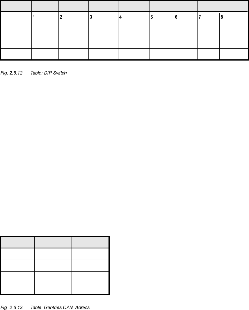
Jumper 7, 8: CAN_ID:
6WDQGDUG 2)) 2)) 2)) 2)) 21 21 &$1B$GUHVV
Position
of switch
CAN_R120 EPROM_WE Test_Mode CAN_ERR_
SWITCH
Jumper 5 Jumper 6 CAN_ID1 CAN_ID0
21 ; ;
2)) ; ; ; ;
*DQWULHV -XPSHU -XPSHU
Gantry 1 21 21
Gantry 2 21 2))
Gantry 3 2)) 21
Gantry 4 2)) 2))
Retrofitting Instructions SIPLACE Modular Head PCB on S-23, S-25 HM, F5 HM, HS-50
02/2003 Edition 2.6 Installing the Head PCB, Modular
65
$VVHPEOLQJWKH3ODFHPHQW+HDGDQGWKH0DFKLQH
Å
Place the covers previously removed back on the placement heads (see NOTE in Section 2.1).
Fasten the covers with 5 screws each.
Currently there is no cover on the HS-50.
Å Remove all of the tools, etc., from the machine’s working area.
Å Before docking the movable component changeover table, push the gantry until it is over the
PCB conveyor area.
-> During this process, be careful to observe the minimum distances of the X-gantries so that
the crash switch(es) is/are not actuated.
Å Lock the doors of the machine frame.
Å If the component changeover tables have been undocked:
Å Turn the machine ON at the main switch. The compressed air must be connected
Å Dock all movable component changeover tables (if applicable the MTC an S-25 HM) with
the previous allocation.
Å Install the cover of the feeder modules over the component changeover tables.
Å Close the safety doors and safety hoods.
Å On S-25 HM and S-23 continue with the setting of the X-track signals (see Section 2.6.8).