00192393-02.pdf - 第69页
Retrofitting Instr uctions SIP LACE Modular Head PCB on S-23, S-25 HM, F5 HM, HS-50 02/2003 Edition 2.6 Installing the Head PCB, Modular 67 Connectio n of 2nd flash line to gantry conver ter board o n S23 / S25 HM / F 5H…
Modular Head PCB on S-23, S-25 HM, F5 HM, HS-50 Retrofitting Instructions SIPLACE
2.6 Installing the Head PCB, Modular 02/2003 Edition
66
2QO\RQ6DQG6+06HWWLQJ;7UDFN6LJQDOV
The identical procedure is followed when setting the S-23 and the S-25 HM. Therefore you can
also proceed for the S-23 as specified in the Setting Instructions for SIPLACE S-25 HM, Item no.
00192192-02 (G + E).
For the setting on S-23/25 HM you will need the auxiliary test equipment specified in the Setting
Instructions (section "Gantries" -> "Track Signals" -> "Auxiliary Equipment").
As the final step, set the X-track signals on the head PCB, modular, on the S-23 and the S-25
HM as described in the section "Gantries" -> "Track Signals".
2QO\66+0)+0
After installing the new head board modular head board S25 (00353198-02) or gantry head distri-
butor board F5 HM (00354432-02), on older S23 / S25 HM / F5HM machines, the error message
" 272 Vision system not providing meas. results“ is issued and components are often rejected.
&DXVHRIWKHIDXOW
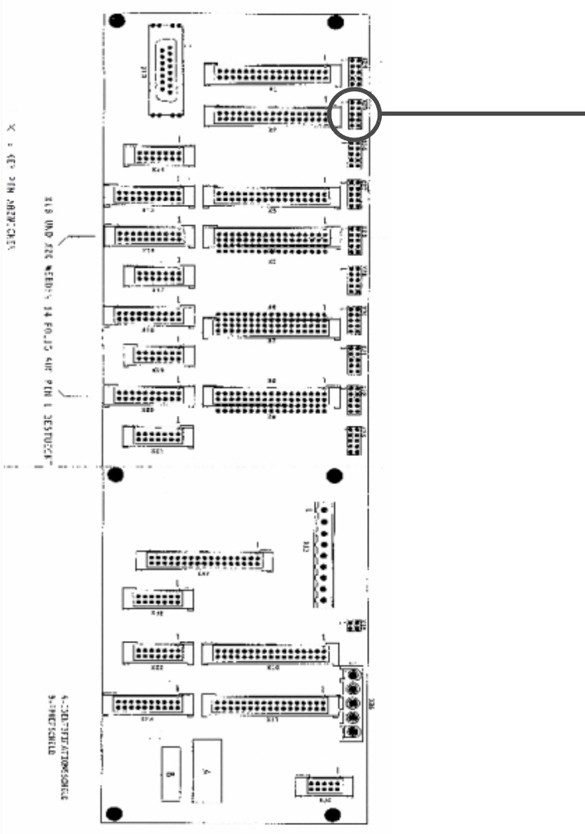
On the gantry converter board C0003 (see diagram) the brown wire is not connected to Pin 2 on
connector X25 (was not used previously). This means that the second flash line from ICOS was
not passed to the head board and the new head board returns errors.
6ROXWLRQ
Å Remove the shrink-sleeve from the brown wire and connect it. (see plan next page).
Retrofitting Instructions SIPLACE Modular Head PCB on S-23, S-25 HM, F5 HM, HS-50
02/2003 Edition 2.6 Installing the Head PCB, Modular
67
Connection of 2nd flash line to gantry converter board on S23 / S25 HM / F5HM:
Brown wire to Pin 2 X25
Modular Head PCB on S-23, S-25 HM, F5 HM, HS-50 Retrofitting Instructions SIPLACE
2.7 Appendix: Circuit Diagrams, Layout (Vision Board) 02/2003 Edition
68
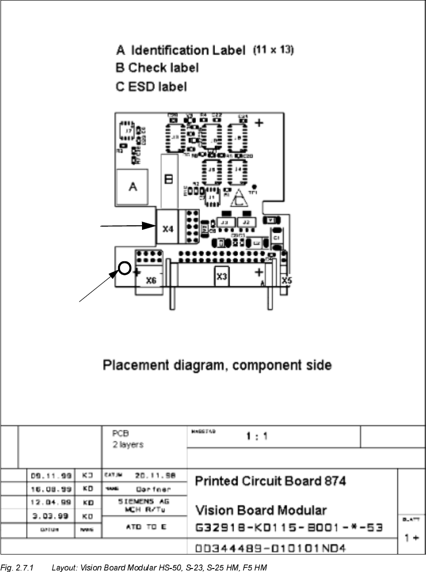
$SSHQGL[&LUFXLW'LDJUDPV/D\RXW9LVLRQ%RDUG
"Camera" of the
PCB Camera:
-> X4
Cable
Hole for fastening the
cable "Camera" with the
cable tie (= version -02 of the PCB)
Multicolor or
Normal Illumination
PCB Camera with