88192278-01-19 Installation Master.pdf - 第101页
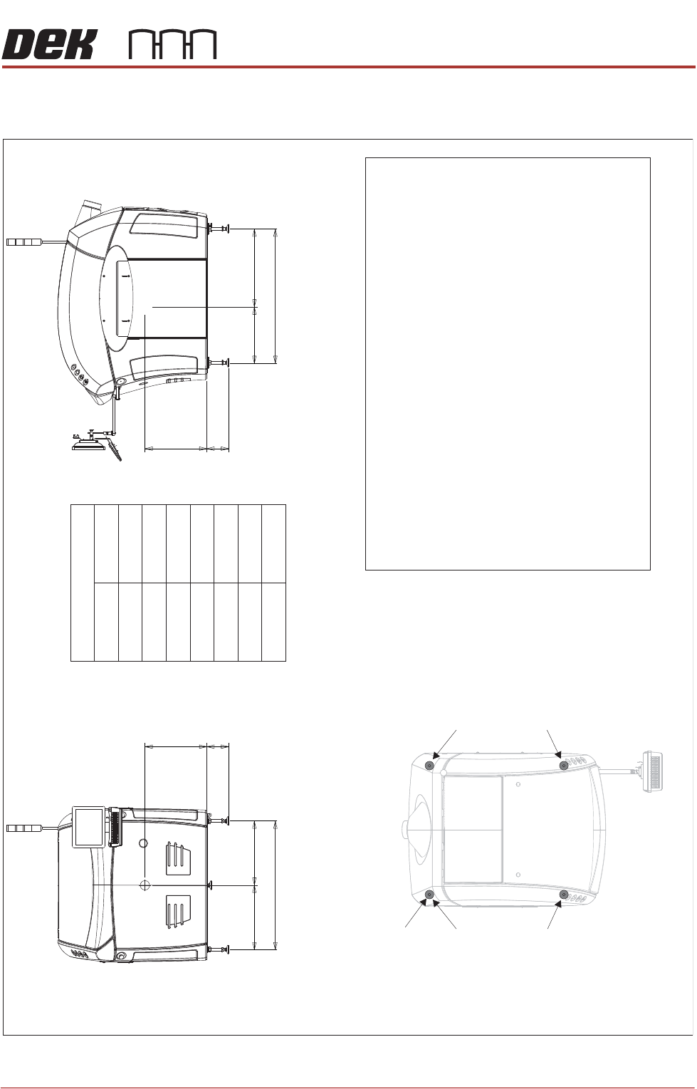
SERVICES REQUIRED CENTRE OF GRAVITY AND SEISMIC ANCH ORAGE Chapter Issue 16, Nov 19 Installation Manual 3.11 CENTRE OF GRA VITY AND S EISMIC ANCHORAGE Figure 3-9 T ype 1 Covers (Only) Side View (right) CG L2 a b h L1 Fro…
SERVICES REQUIRED
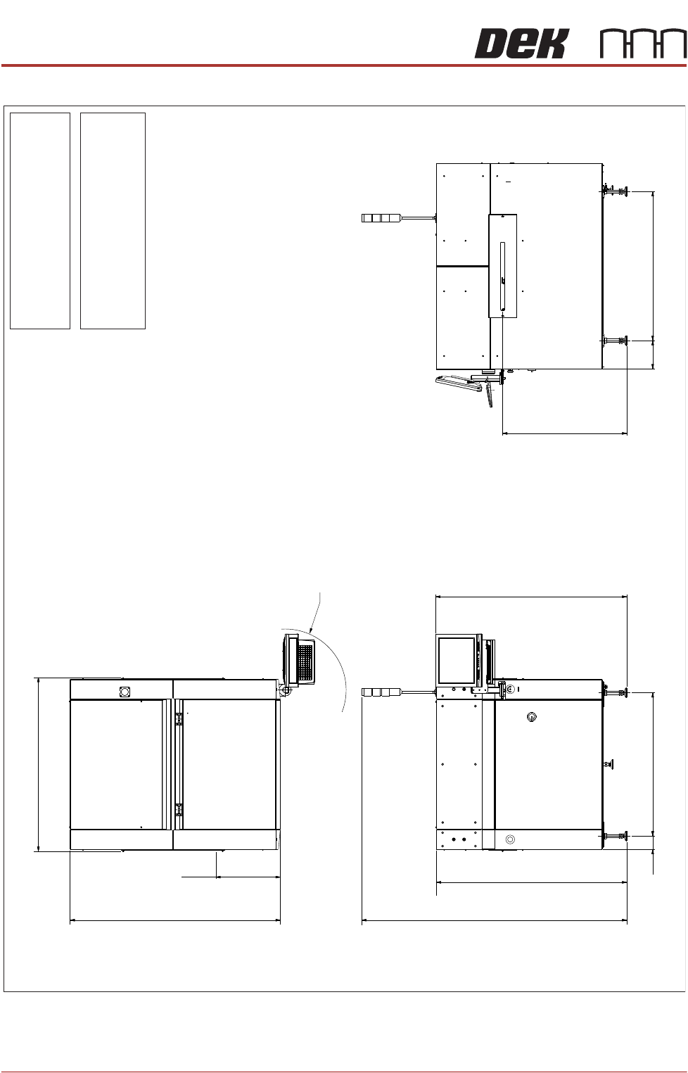
PRINTER FOOTPRINTS
3.10 Installation Manual Chapter Issue 16, Nov 19
Figure 3-8 Type 5 Covers
Weight
Boxed - 8 kg, Unboxed - 6 kg10 54
(Dependent upon configured options
selected with the machine
)
Note
All dimensions in millimetres
Board transfer height 8 - 980 mm40
Screen load height 925 - 1065 mm
219
1150
Transfer Height 960
(840 min to 980 max)
Side View (Right)
1342
Front of Board
499
1624
R455
Max dimension from
pivot point
Plan View
1106
(1357 min to 1497 max.)
1477
104
Front View
(1929 min to 2069 max.)
2049
(1352 min to 1492 max.)
1472
SERVICES REQUIRED
CENTRE OF GRAVITY AND SEISMIC ANCHORAGE
Chapter Issue 16, Nov 19 Installation Manual 3.11
CENTRE OF GRAVITY AND SEISMIC ANCHORAGE
Figure 3-9 Type 1 Covers (Only)
Side View (right)
CG
L2
a
b
h
L1
Front View
CG
L3
d
b
h
c
Centre of Gravity
a
b
c
d
h
L1
L2
L3
1150mm
130mm
1106mm
530mm
485mm
565mm
665mm
541mm
Plan View
Centre of Gravity
Seismic Anchorage
Machine Feet
(in 4 positions
)
Min = -100kg
Max = +400kg
Min = -100kg
Max = +400kg
Min = -100kg
Max = +400kg
Min = -100kg
Max = +400kg
Seismic Anchorage
The calculations for the downward and upward force of the feet
is calculated in line with the 1997 Uniform Building Code and
SEMI S2-0703. Results indicate that under worse circumstances
(calculation for hazardous fluids
) an upward lifting force has to be
expected and it is strongly recommended to secure the machine
directly to the floor.
NOTE
In the figure on the left, negative numbers are upward loads and
positive numbers are downward loads.
Appropriate attachment points may be fitted to the front and rear
of the machine base frame. For more information, contact DEK
Printing Machines.
Alternatively, the supplied machine feet can be replaced with feet
incorporating holes allowing the feet to be secured directly to the floor.
Additional seismic calculations must be undertaken for the floor and
any anchor points that are used.
The length of the machine feet
(measurement
in the figures above
)
b
must not exceed 130mm to meet seismic anchorage calculations.

SERVICES REQUIRED
CENTRE OF GRAVITY AND SEISMIC ANCHORAGE
3.12 Installation Manual Chapter Issue 16, Nov 19