88192278-01-19 Installation Master.pdf - 第104页
PRINTER PREPARATION GENERAL 4.2 Installation Manual Chapter Issue 15, May 20 1. Locate the forks under the printer base . 2. Raise the forks, separating the printer from the base of the transpo rtation box. 3. For printe…

PRINTER PREPARATION
GENERAL
Chapter Issue 15, May 20 Installation Manual 4.1
CHAPTER 4 PRINTER PREPARATION
GENERAL Prior to printer power up it is essential to follow the preparation instructions in
this section thus ensuring correct operation of the printer and prevent any
possible damage occurring to the printer or personnel.
NOTE
Do not remove the red transit brackets, tie wraps or screws attached to the
printer until the printer has been moved to its designated position.
Using the Pack List, ensure that all items are supplied.
Visually inspect all printer components and equipment for completeness,
condition and damage. If any components or equipment are incomplete,
damaged or in poor condition, make a note of this on the Outstanding Issues
page found in the Installation Documentation chapter of this manual.
Transportation
WARNING
MACHINE LIFTING. TO PREVENT SERIOUS INJURY TO PERSONNEL, DURING
LIFTING AND TRANSPORTATION OPERATIONS, ENSURE THE MACHINE IS
LIFTED AND TRANSPORTED IN ACCORDANCE WITH INSTRUCTIONS DETAILED
IN THIS SECTION.
NOTE
Damage to the printer will occur if the printer is lifted:
• Using lifting strops
OR...
• From the sides
ASM recommends that the printer is lifted from the rear at all times however,
the printer may be lifted from the front if the printer is to be moved a short
distance or moved into line.
The printer may be lifted using a forklift truck or similar printer that meets the
following criteria:
• Minimum fork length of 1372mm (54 inches)
• Fork span >686mm (27 inches) and <914mm (36 inches)
• Fork Height (thickness) <50mm (2 inches)
• Lifting capability of 2000kg

PRINTER PREPARATION
GENERAL
4.2 Installation Manual Chapter Issue 15, May 20
1. Locate the forks under the printer base.
2. Raise the forks, separating the printer from the base of the transportation
box.
3. For printers with the anti-vibration mounting option, four leg spacers and one
standard foot is supplied. Ensure the correct number of leg spacers are fitted
to the four corners of the printer when it is located into the production line.30
4. Move the printer to its designated position.
PRINTER PREPARATION
GENERAL
Chapter Issue 15, May 20 Installation Manual 4.3
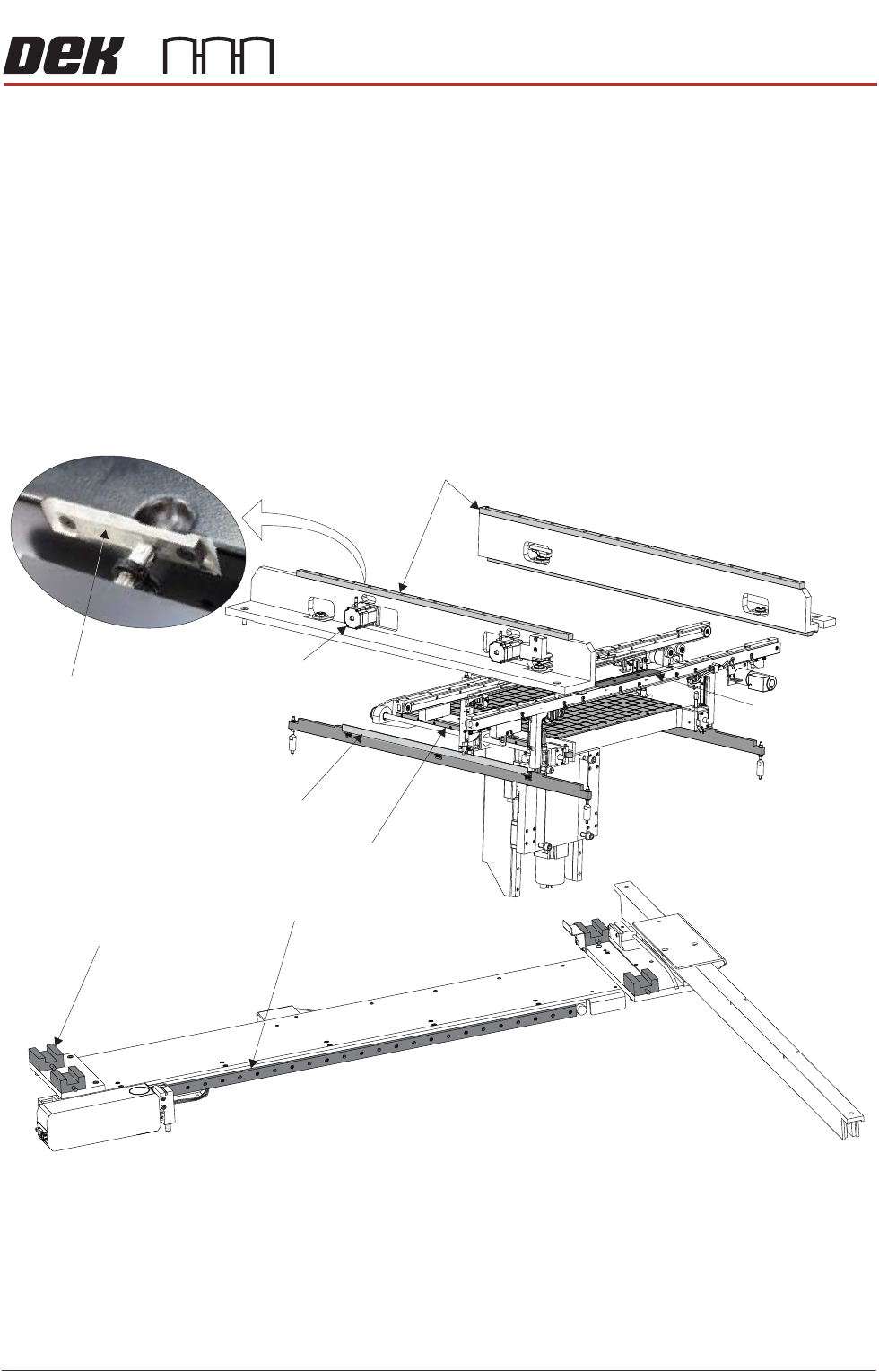
Grease Protection Before the printer was packaged, some areas within the printer were coated
with LM grease or multi-purpose oil to protect the metal surfaces from corroding
during transportation.
Using a lint free cloth, remove any surplus grease from the following areas,
ensuring that a light coating remains:
• Print carriage linear bearing guides (above the printheads)
• Camera linear bearing guides (below the printheads)
• Rear moving rail linear bearing guides (either side of the rising table)
• Top face of both clatter bars (either side of the rising table)
• Actuator striker plates (in 3 positions)
Figure 4-1 Grease Protection
Print Carriage Linear Bearing Guides
Moving Rail Linear Bearing Guide (in 2 positions)
Clatter Bar (in 2 positions)
Board Clamp
(in 2 positions)
Camera Linear Bearing GuideX
Camera Linear Bearing GuideY
(4 Positions)
Actuator (in 3 positions)
Actuator Striker Plate
(in 3 positions)