88192278-01-19 Installation Master.pdf - 第112页
PRINTER PREPARATION TRANSIT BRACKETS AND SCREWS REMOVAL 4.10 Installation Manual Chapter Issue 15, May 20 Print Carriage Tr a n s i t S c r e w 1. Loosen the M8 locking nut that se cures the transit screw to the prin t c…
PRINTER PREPARATION
TRANSIT BRACKETS AND SCREWS REMOVAL
Chapter Issue 15, May 20 Installation Manual 4.9
1. Using a 4mm Allen key loosen the two M5 cap head screws (2), crinkle
washers (3) and washers (4) sufficiently to allow movement in the block (6).
2. Using a 10mm spanner loosen the M6 nylon screws (5) sufficiently to allow
the block to lift from the carriage rail, but do not remove.
3. Remove and retain the M5 cap head screws (7), crinkle washers (8) and
washers (9) using a 4mm Allen Key holding the bracket (1) to the covers
frame.
4. Remove the transit bracket (1) and block (6) as an assembly.
NOTE
After the transit bracket / block assembly has been removed, it is recommended
that the retained screws, crinkle washers and washers are refitted through the
neoprene washers on the covers frame and the previously loosened screws on
the assembly are tightened to prevent loss.
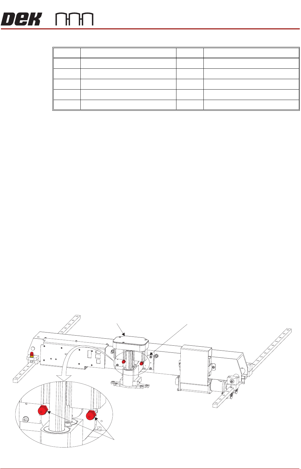
Transit Screws
Squeegee Transit
Screws
1. Snip the cable ties securing the piece of card to the front of the squeegee
mechanism. Remove the cable ties and the piece of card from the printer.
2. Whilst supporting the squeegee mechanism, remove the two squeegee
transit screws.
Item Description Item Description
1 Cover Frame Transit Bracket 6 Block
2 M5 Cap Head Screw 7 M5 Cap Head Screw
3 M5 Crinkle Washer 8 M5 Crinkle Washer
4M5 Washer 9M5 Washer
5 M6 Nylon Screw
Squeegee Transit Screws
Squeegee Mechanism Squeegee Mount
PRINTER PREPARATION
TRANSIT BRACKETS AND SCREWS REMOVAL
4.10 Installation Manual Chapter Issue 15, May 20
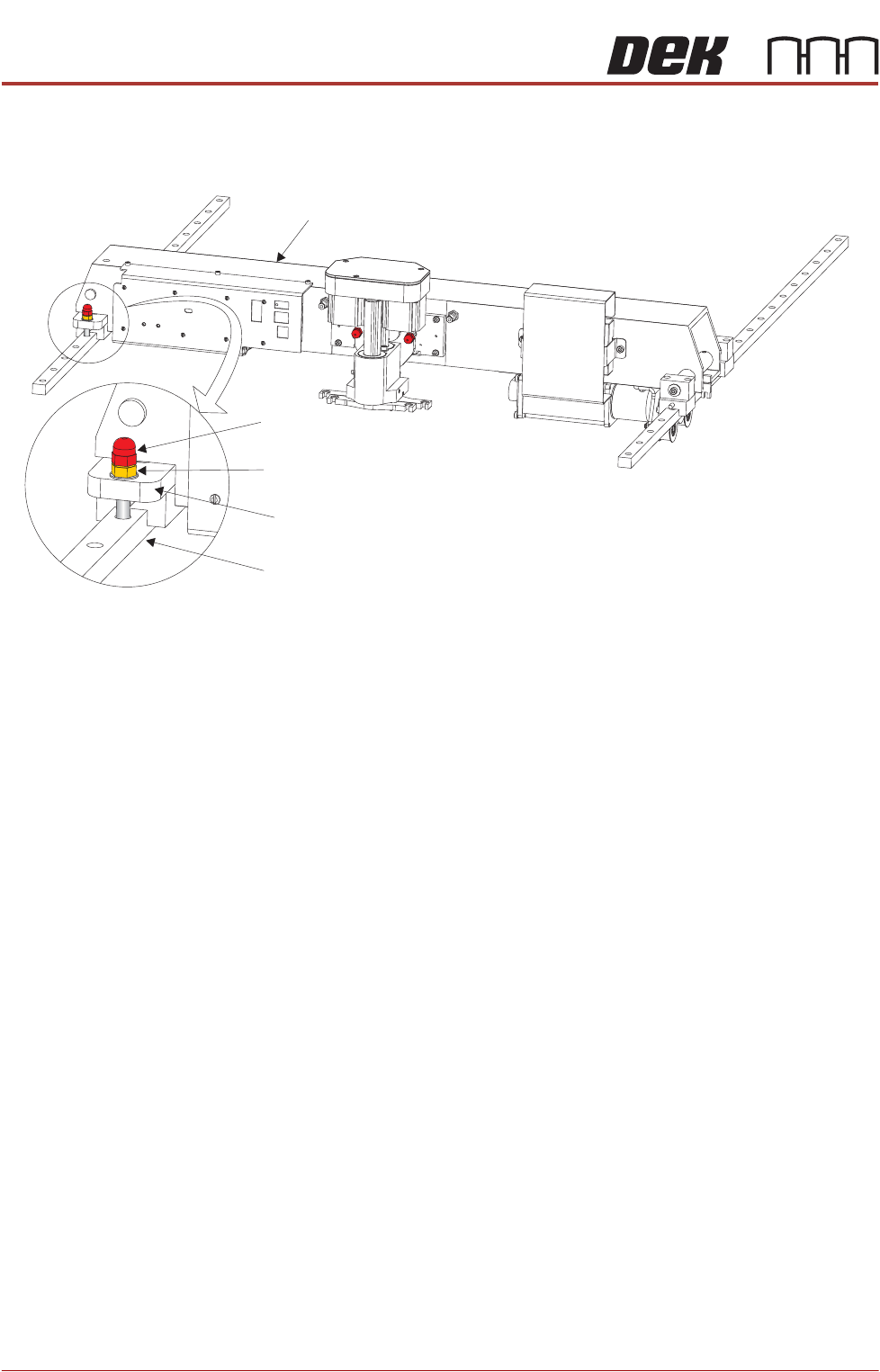
Print Carriage
Transit Screw
1. Loosen the M8 locking nut that secures the transit screw to the print carriage
compliant bearing block.
2. Remove the print carriage transit screw that secures the print carriage
compliant bearing block to the left linear guide rail. Ensure that the crinkle
washer below the locking nut is also removed.
3. Locate the re-sealable polythene bag taped to the print carriage.
4. Remove the plastic cap from the bag and fit into the hole that the transit
screw occupied on the left linear guide rail.
Print Carriage
Transit Screw
Print Carriage Compliant Bearing Block
Left Linear Guide Rail
Locking Nut and Crinkle Washer
PRINTER PREPARATION
TRANSIT BRACKETS AND SCREWS REMOVAL
Chapter Issue 15, May 20 Installation Manual 4.11
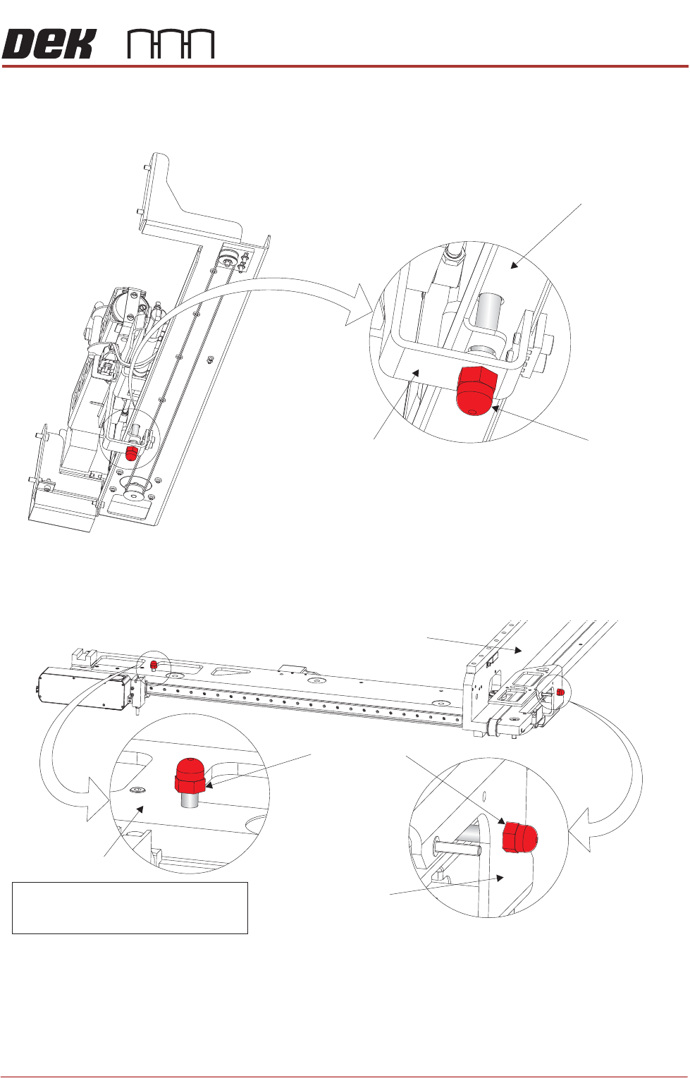
Paste Dispenser
Transit Screw
1. Remove the paste dispenser transit screw that secures the belt clamp
bracket to the paste dispenser mounting tray.
Camera Transit
Screws (Rotary
Drive)
1. Remove the transit screw that secures the camera beam to the camera X
drag chain bracket.
2. Remove the transit screw that secures the camera Y drag chain bracket to
the right hand printhead.
View on Right Hand Underside of Paste Dispenser
Transit Screw
Paste Dispenser Mounting Tray
Belt Clamp Bracket
Note
Camera X Drag Chain Bracket is hidden
from view by the Camera Beam
Transit Screws
Camera Beam
Right Hand Printhead
Camera Y Drag
Chain Bracket