88192278-01-19 Installation Master.pdf - 第116页
PRINTER PREPARATION PRINTER HEIGHT AND LEVELLING 4.14 Installation Manual Chapter Issue 15, May 20 T ype 1, 2, 3 and 5 Printers Before operation, the printer must be installed at t he correct height and levelled. The hei…
PRINTER PREPARATION
PRINTER HEIGHT AND LEVELLING
Chapter Issue 15, May 20 Installation Manual 4.13
PRINTER HEIGHT AND LEVELLING
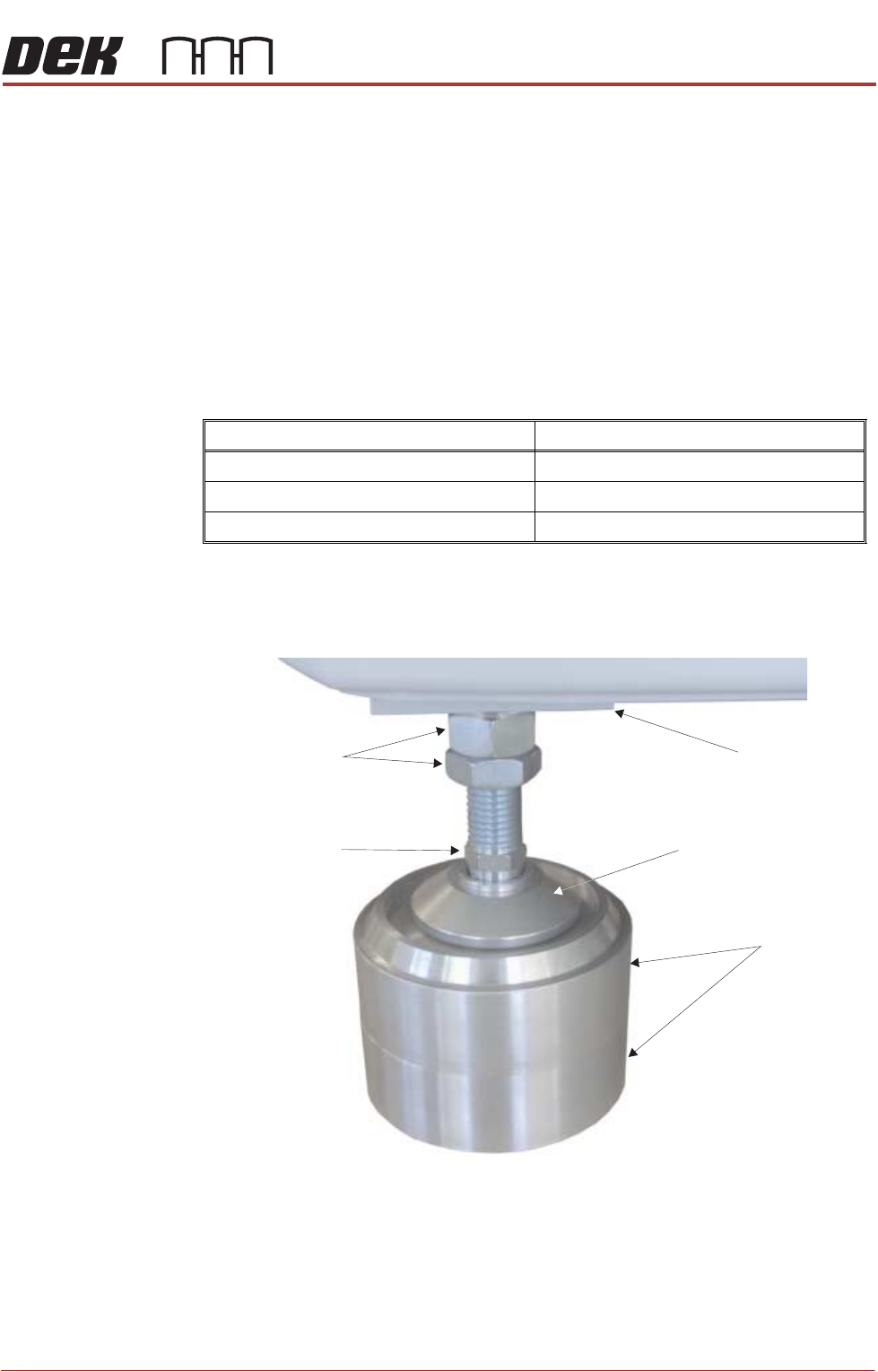
Leg Spacers
(Camera Linear
Drive Printer Only)
The mounting feet on the camera linear drive printer must be kept as short as
possible to reduce vibration and oscillation.
To achieve the height required, 8 leg spacers (maximum of two per foot) are
supplied. The leg spacers interlock together and the printer foot locates in the
recess of the top leg spacer.
1. Using the table below, determine the amount of leg spacers to achieve the
required printer height:
NOTE
The amount of exposed thread of the printer leg should be kept to a mini-
mum to ensure printer accuracy remains within limits.
2. Place the correct number of leg spacers under each corner mounting foot.
Do not place leg spacers under the centre rear mounting foot. Lower the
printer ensuring that each foot is located inside the recessed top, figure
below refers.
NOTE
Do not attempt to manoeuvre the printer into position whilst mounted on the
leg spacers. The printer must be lifted, moved and lowered ensuring that
the leg spacers are moved with the printer.
Transport Height Leg Spacers Required
840mm - 895mm 0
896mm - 940mm 1
941mm - 980mm 2
Leg Spacers
(2 shown)
Machine Mounting Foot
M24 Locking Nuts
Machine Frame
Leg Adjusting Nut
PRINTER PREPARATION
PRINTER HEIGHT AND LEVELLING
4.14 Installation Manual Chapter Issue 15, May 20
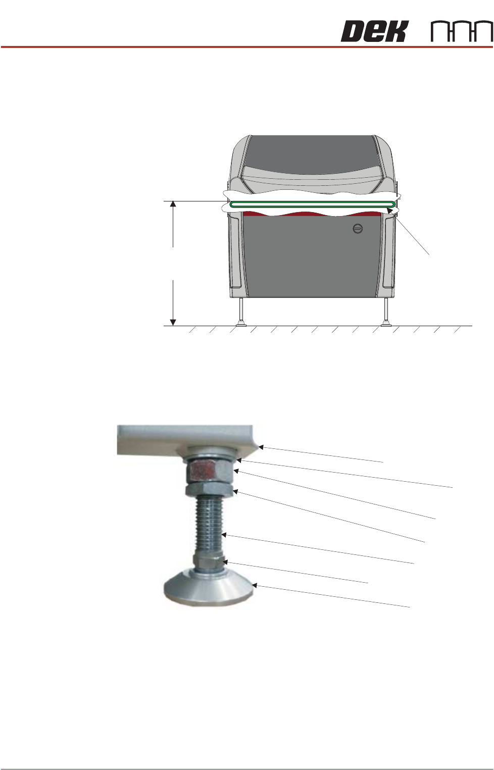
Type 1, 2, 3 and 5
Printers
Before operation, the printer must be installed at the correct height and levelled.
The height of the printer is governed by the external printers that it is to be
connected to and ranges from 840mm to 980mm. The height is measured from
the floor to the top of the transport belts.
The transport height may be adjusted as low as 830mm by removing the M24
full nut on each of the legs. In the event of the transport height being adjusted
above 839mm at a later date, the M24 full nut must be refitted.
NOTE
To achieve reliable DEK SPC testing and Cp/Cpk results, the printer legs must
be secured correctly to the frame to increase the rigidity of the printer.
Height to Top
of Transport Belts
840mm to 980mm
View on Front of Machine
Transport Belts
Washer
Machine Frame
Full Nut
Half Nut
Leg Adjusting Nut
Leg Bolt
Foot
PRINTER PREPARATION
PRINTER HEIGHT AND LEVELLING
Chapter Issue 15, May 20 Installation Manual 4.15
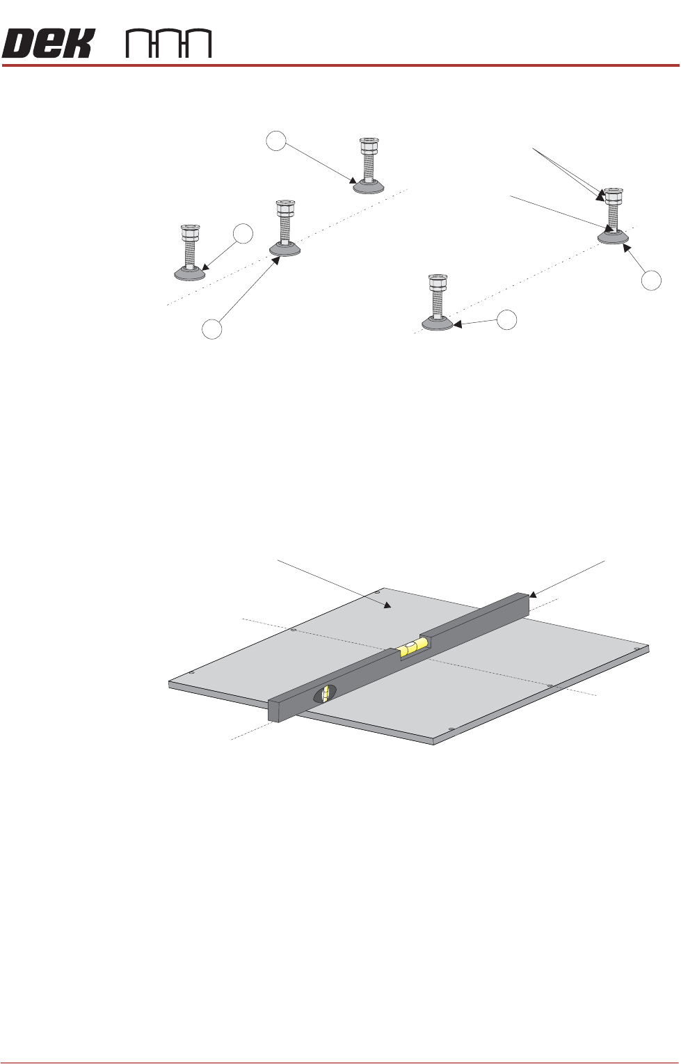
1. Adjust the front right hand foot (1) to achieve the desired height.
2. Adjust the front left hand foot (2) to approximately the same height.
3. Lower the rear centre mounting foot (3) so that it is in contact with the floor.
4. Raise the rear left (4) and rear right (5) mounting feet so they are not in
contact with the floor/leg spacers and the printer is supported on the front
two and rear centre mounting feet.
5. Place an engineering level on top of the manual tooling plate along the front
row of screws running from left to right.
6. Adjust the front left (2) mounting foot to level the printer in the X direction.
7. Move the engineering level along the centre row of screws running from front
to back.
8. Adjust the rear centre (3) mounting foot to level the printer in the Y direction.
9. Repeat Steps 5 to 8 until the printer is level in both directions.
10. Carefully lower the rear left mounting foot (4) so that it is in contact with the
floor/leg spacer. Check the printer level has not been disturbed.
11. Carefully lower the rear right mounting foot (5) so that it is in contact with the
floor/leg spacer. Check the printer level has not been disturbed.
12. Raise the rear centre mounting foot (3) so it is not in contact with the floor.
13. Lock off all five mounting feet using the locknuts.
Isometric View on Machine Mounting Feet
Locking Nuts
Front
4
3
2
1
Leg Adjuster
5
Engineering LevelManual Tooling Plate
Isometric View on Manual Tooling Plate
Front
Centre Line
(Y direction)
Centre Line
(X direction)