88192278-01-19 Installation Master.pdf - 第118页
PRINTER PREPARATION PRINTER HEIGHT AND LEVELLING 4.16 Installation Manual Chapter Issue 15, May 20 14. R echeck the printer is level. 15. R echeck the printer height has n ot been disturbed. 16. R emove the engineering l…
PRINTER PREPARATION
PRINTER HEIGHT AND LEVELLING
Chapter Issue 15, May 20 Installation Manual 4.15
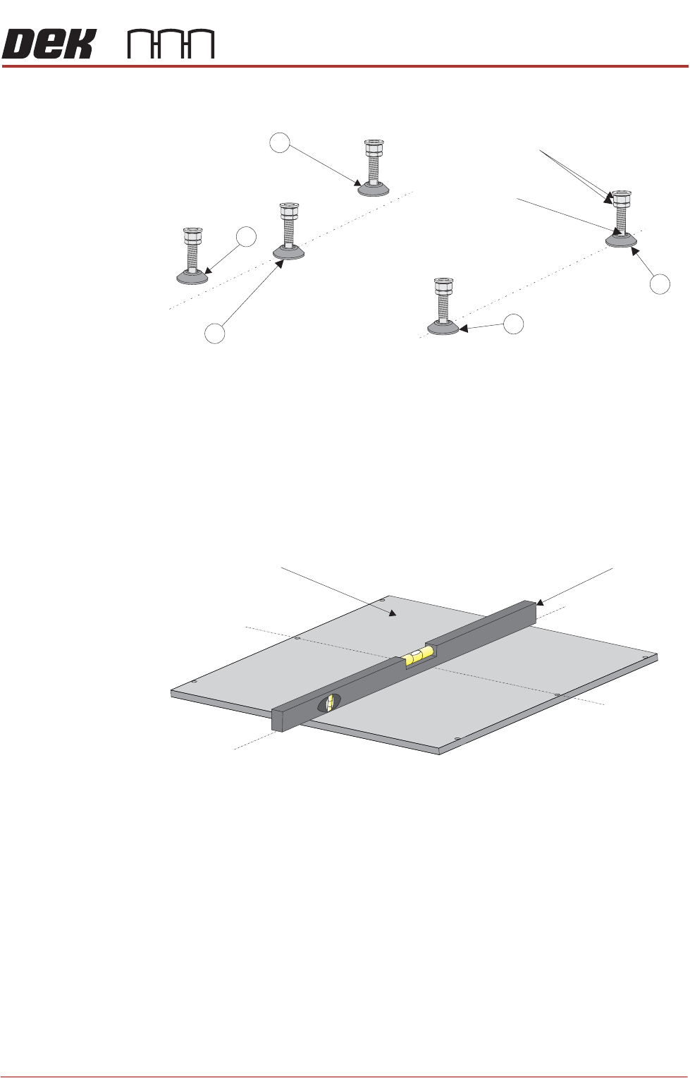
1. Adjust the front right hand foot (1) to achieve the desired height.
2. Adjust the front left hand foot (2) to approximately the same height.
3. Lower the rear centre mounting foot (3) so that it is in contact with the floor.
4. Raise the rear left (4) and rear right (5) mounting feet so they are not in
contact with the floor/leg spacers and the printer is supported on the front
two and rear centre mounting feet.
5. Place an engineering level on top of the manual tooling plate along the front
row of screws running from left to right.
6. Adjust the front left (2) mounting foot to level the printer in the X direction.
7. Move the engineering level along the centre row of screws running from front
to back.
8. Adjust the rear centre (3) mounting foot to level the printer in the Y direction.
9. Repeat Steps 5 to 8 until the printer is level in both directions.
10. Carefully lower the rear left mounting foot (4) so that it is in contact with the
floor/leg spacer. Check the printer level has not been disturbed.
11. Carefully lower the rear right mounting foot (5) so that it is in contact with the
floor/leg spacer. Check the printer level has not been disturbed.
12. Raise the rear centre mounting foot (3) so it is not in contact with the floor.
13. Lock off all five mounting feet using the locknuts.
Isometric View on Machine Mounting Feet
Locking Nuts
Front
4
3
2
1
Leg Adjuster
5
Engineering LevelManual Tooling Plate
Isometric View on Manual Tooling Plate
Front
Centre Line
(Y direction)
Centre Line
(X direction)

PRINTER PREPARATION
PRINTER HEIGHT AND LEVELLING
4.16 Installation Manual Chapter Issue 15, May 20
14. Recheck the printer is level.
15. Recheck the printer height has not been disturbed.
16. Remove the engineering level from the printer.
PRINTER PREPARATION
PRINTER HEIGHT AND LEVELLING
Chapter Issue 15, May 20 Installation Manual 4.17
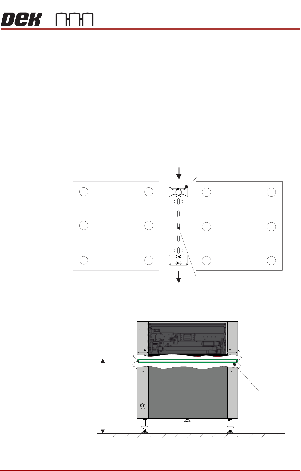
Type 4 Printers Before operation, Printers A and B must be installed at the correct height,
levelled and aligned using the supplied Location Plate Assembly.
NOTE
1. The orientation of the machine location plate is normally in the upline to
downline direction with the ‘V’ plates nearest the upline end. However,
where there is an item, such as the pneumatic inlet connector, in the vicinity
of the ‘V’ plates, the plates need to be located at the opposite end to avoid
creating an obstruction. Turn the location plate around. In the following
procedure, references to feet numbers at the rear of the printer now apply
to feet located at the front.
2. The ‘V’ plates can be removed and moved to opposite corners if the printers
have air inlet connectors located on opposite corners.
For this procedure, refer to the following diagram indicating feet numbers.
The height of each printer is governed by the external machines in the line, and
ranges from 840mm to 980mm. The height is measured from the floor to the top
of the transport belts.
Height to Top
of Transport Belts
8 mm to 980mm95
View on Front of Machine
Transport Belts