88192278-01-19 Installation Master.pdf - 第121页
PRINTER PREPARATION PRINTER HEIGHT AND LEVELLING Chapter Issue 15, May 20 Installation Manual 4.19 2. Move printer A into position and align it with the downline p rinter using two rectangular PCBs. 3. Using recommended …
PRINTER PREPARATION
PRINTER HEIGHT AND LEVELLING
4.18 Installation Manual Chapter Issue 15, May 20
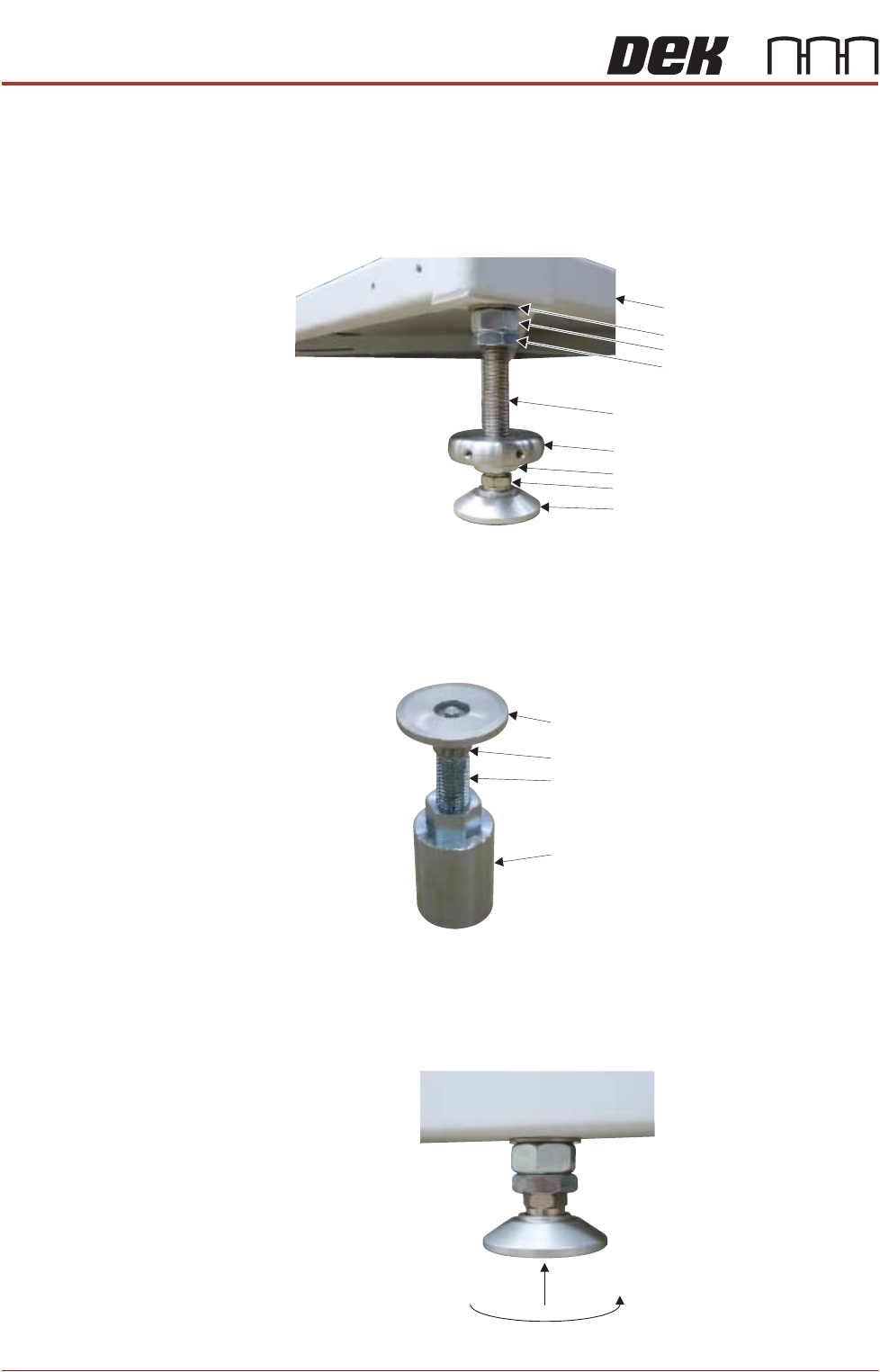
The transport height may be adjusted as low as 830mm by removing the M24
full nut on each of the legs. In the event of the transport height being adjusted
above 839mm at a later date, the M24 full nut must be refitted. The locating
collar positions the printer accurately against the V-blocks on the Locator Plate
Assembly.
NOTE
To achieve reliable DEK SPC testing and Cp/Cpk results, the printer legs must
be secured correctly to the frame to increase the rigidity of the printer.
NOTE
The centre mounting foot (6) is separate and is only used for initial levelling.
Levelling and
Positioning (Printer
A)
1. Raise the rear centre mounting foot (5) to the highest position to avoid
contact with the floor plate.
Washer
Machine Frame
M24 Full Nut
Half Nut
Locating Collar
Leg Bolt
Foot
Half Nut
Leg Adjusting Nut
Swivel Plate
Foot
Leg Bolt
Full Nut
PRINTER PREPARATION
PRINTER HEIGHT AND LEVELLING
Chapter Issue 15, May 20 Installation Manual 4.19
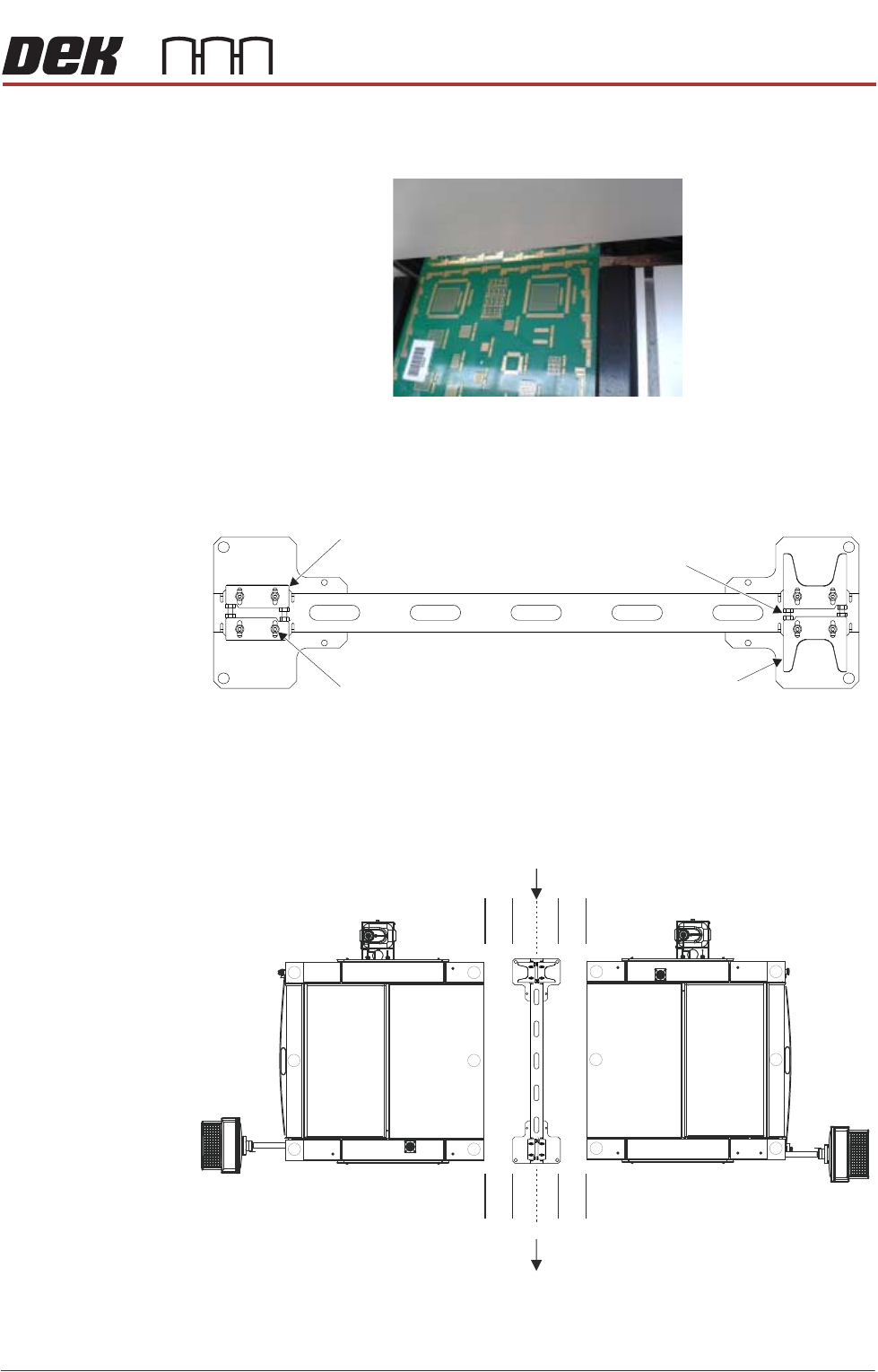
2. Move printer A into position and align it with the downline printer using two
rectangular PCBs.
3. Using recommended lifting equipment, carefully raise the printer
approximately 10mm off the floor. Avoid any movement in direction X and Y.
4. Check the location blocks and V-blocks on the floor plate are free to move
in X and Y.
5. Check that all four stopper bolts are fully wound in.
6. Place the floor plate under foot (3) and foot (4) of printer A ensuring the
orientation of the floor plate is correct.
7. Ensure the floor plate is positioned inline with foot (3) and foot (4) and
parallel to the rear of the printer (shown above).
Location Blocks x 2
Stopper Bolts
and locking nuts x4
V-Block x 2
Location Block Fixing Screws x 4
Plan Floor PlateView on Machine
/,1(',5(&7,21
0$&+,1(
%
0$&+,1(
$
PRINTER PREPARATION
PRINTER HEIGHT AND LEVELLING
4.20 Installation Manual Chapter Issue 15, May 20
8. Lower the printer onto the floor plate, ensuring foot (3) and foot (4) are
positioned correctly on the plate and clear of the location and V- blocks.
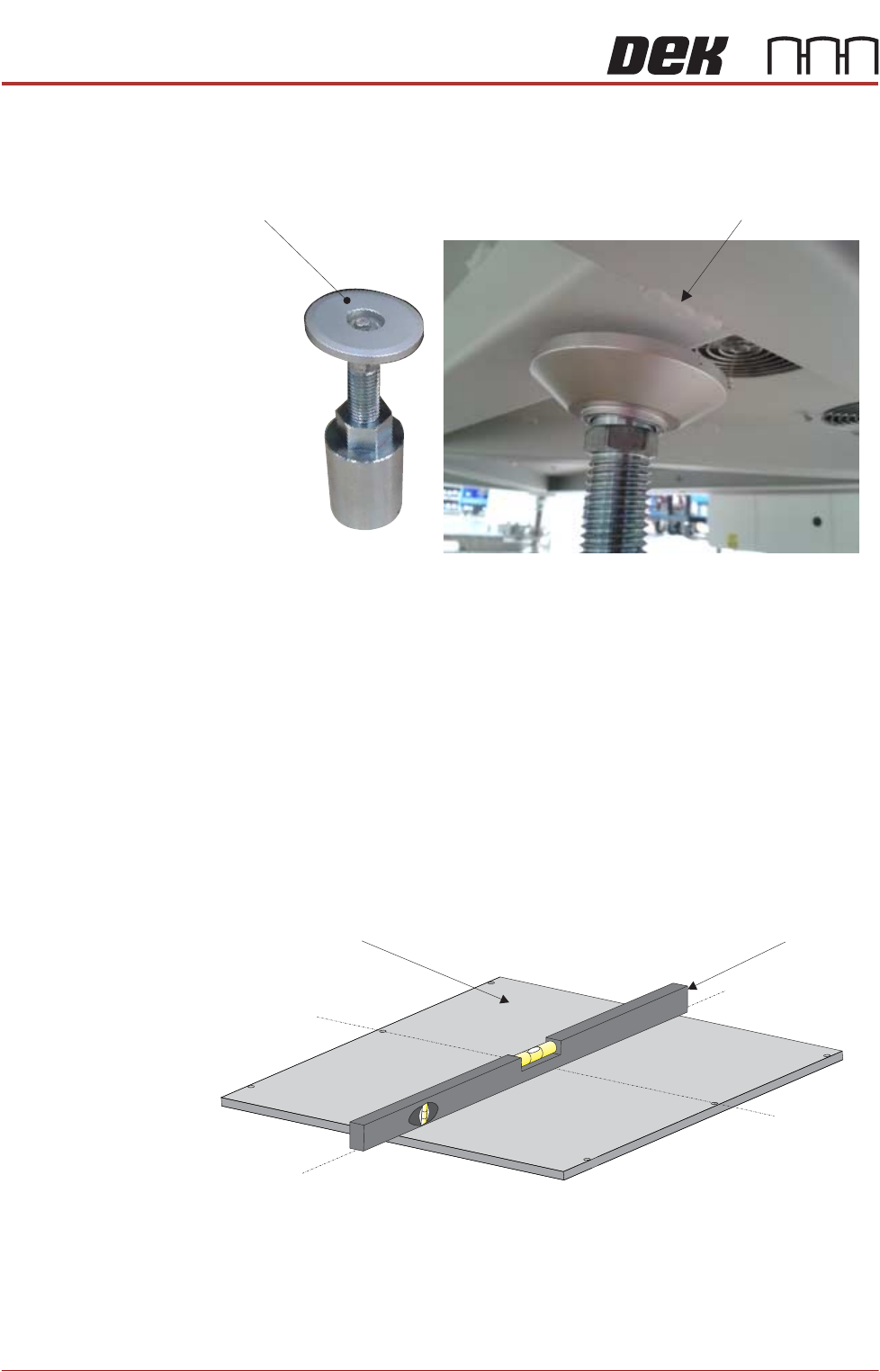
9. Place foot (6) under the front of the printer in the centre.
10. Check the orientation of foot (6) as shown above.
NOTE
Avoid the seam weld to ensure the printer is properly supported.
11. Raise the front centre levelling foot (6) to make contact with the printer.
12. Raise the front left foot (1) and front right foot (2) so they are not in contact
with the floor and the printer is supported on the centre mounting foot (6).
13. Apply pneumatic power to the printer to set the rails to the correct height for
printer levelling.
14. Place an engineering level on top of the manual tooling plate along the front
row of screws running from left to right.
15. Adjust the rear mounting foot (3) and foot (4) to level the printer in the X
direction.
16. Move the engineering level along the centre row of screws running from front
Seam WeldLevelling Foot (6)
Front below FrameView Machine
Engineering LevelManual Tooling Plate
Isometric View on Manual Tooling Plate
Front
Centre Line
(Y direction)
Centre Line
(X direction)