88192278-01-19 Installation Master.pdf - 第129页
PRINTER PREPARATION PRINTER ASSEMBLY Chapter Issue 15, May 20 Installation Manual 4.27 PRINTER ASSEMBL Y Assemble the following printer compon ents and assemblies: T ricolour Beacon T ype 1 Covers 1. Fit the tricolour be…
PRINTER PREPARATION
CHASE CLAMP CHECK
4.26 Installation Manual Chapter Issue 15, May 20
CHASE CLAMP CHECK
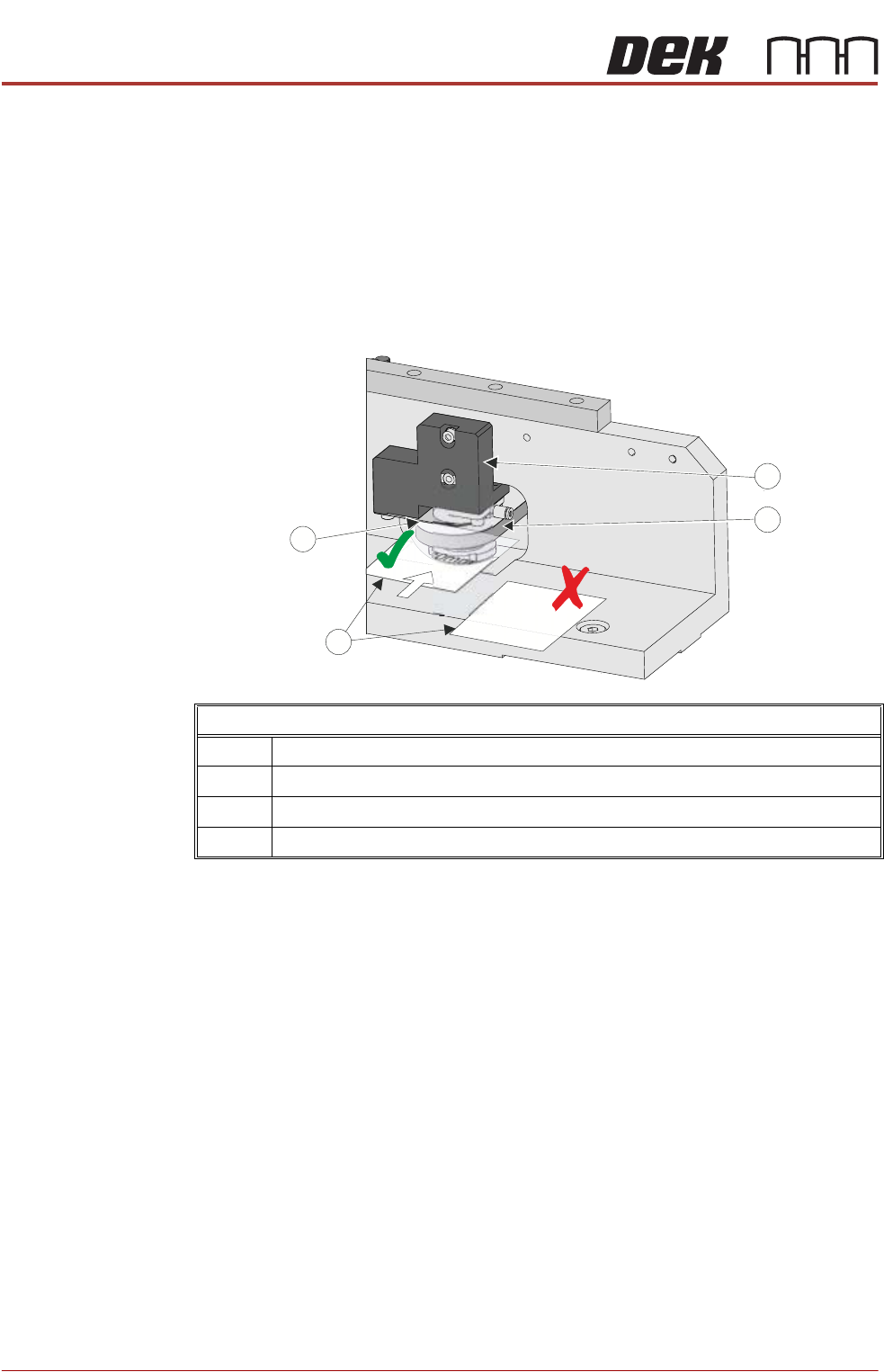
During transportation the chase clamps may have moved out of tolerance; this
can cause poor print results. The chase clamp gaps should be checked and
adjusted where necessary. In factory build, two shims were used as a Go/No
Go gauge to set the gap between the top of the roller counter plate and the
bottom of the clamp plate.
NOTE
Ensure that the printer height and level are set correctly before following this
procedure.
Using the Go/No Go shims check the gap on the left hand front clamp:
1. If the Go gauge cannot be inserted between the clamp plate and the roller
counter plate, go to Step 4.
2. If the Go gauge can be inserted between the clamp plate and the roller
counter plate but the No Go gauge cannot, go to Step 8.
3. If both gauges can be inserted into the gap, go to Step 4.
4. To adjust the clamp, using a 4mm Allen key, slacken off the two M5 cap
headed screws from the pneumatic block, to allow movement.
5. Move the pneumatic block up or down to achieve the gap in Step 2.
6. Using a torque wrench set to 5Nm tighten the screws ensuring the clamp
plate and roller counter plate remain parallel, and the gap is equal across
the width of these plates.
7. Recheck the gap.
8. Repeat the check for the right hand rear clamp.
Chase Clamp Gap Setting
1 Pneumatic Block
2 Roller Counter Plate
3 0.20mm Shim (GO) and 0.25mm Shim (No GO)
4Clamp Plate
PP
PP
PRINTER PREPARATION
PRINTER ASSEMBLY
Chapter Issue 15, May 20 Installation Manual 4.27
PRINTER ASSEMBLY
Assemble the following printer components and assemblies:
Tricolour Beacon
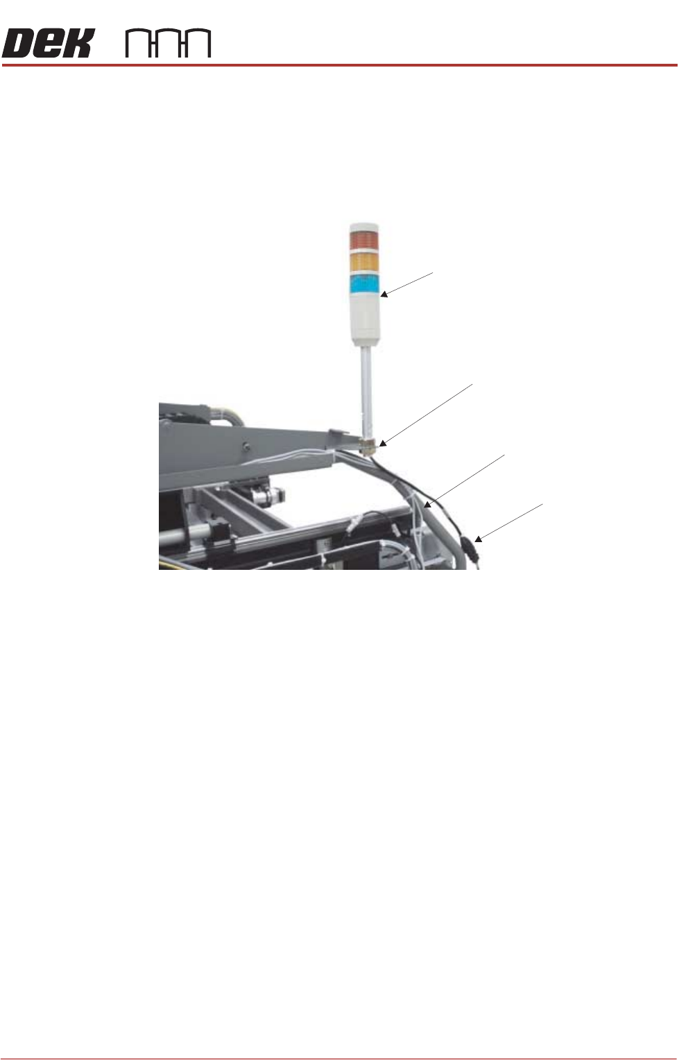
Type 1 Covers 1. Fit the tricolour beacon to the beacon bracket ensuring that the cable is not
trapped between the beacon and the cover frame.
2. Connect the tricolour beacon connection 14PL07 to 14SK07.
3. Cable tie the loose cable to the cover frame.
View on Right Hand Side of Machine (covers removed)
Beacon Connection
Tricolour Beacon
Beacon Bracket
Cover Frame
PRINTER PREPARATION
PRINTER ASSEMBLY
4.28 Installation Manual Chapter Issue 15, May 20
Type 2 Covers 1. Fit the tricolour beacon to the beacon bracket ensuring that the cable is not
trapped between the beacon and the cover frame.
2. Connect the tricolour beacon connection 14PL07 to 14SK07.
3. Cable tie the loose cable to the cover frame.
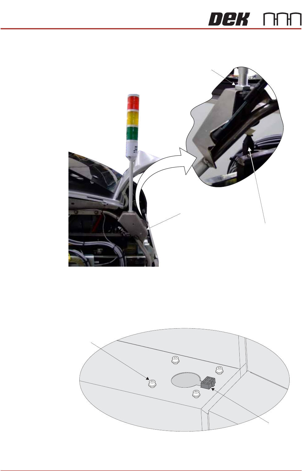
Type 3 Covers 1. Using a 3mm Allen key, remove the beacon bracket securing screws from
the printer cover.
2. Maintaining hold of the socket 14SK07 (to prevent the socket from falling
View on Rear of Printer
Beacon Connection
Beacon Bracket
Beacon Locking Nut
Beacon Bracket
Securing Screws
(in 4 positions)
Beacon Connector
(14SK07)
View on Right Hand Side of the Machine