88192278-01-19 Installation Master.pdf - 第13页
SAFETY FEATURES PRINTER SAFETY FEATURES Chapter Issue 15, Nov 19 Installation Manual 1.1 CHAPTER 1 SAFETY FEA TURES PRINTER SAFETY FEA TURES OVER VIEW The printer incorporates various safety features that provide a safe …
Installation Manual
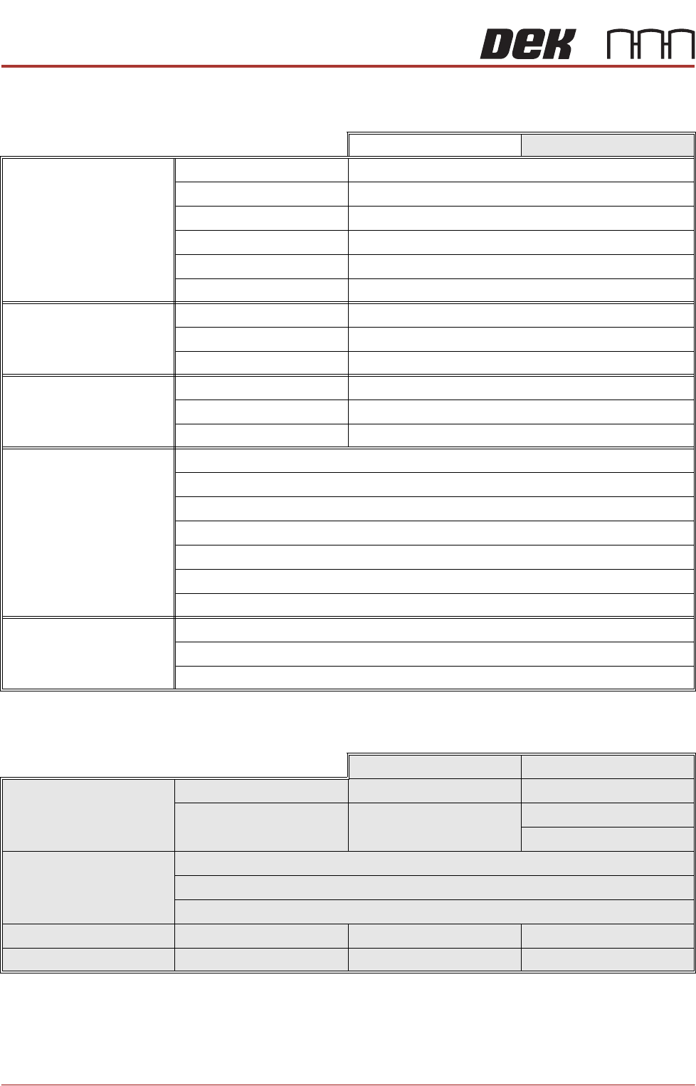
CUSTOMER USE Date
Originator Name & Department
Position
Company
Telephone
Fax
Email
Printer Model Number
Software Version
Serial Number
Manual Title
Chapter
Chapter / Figure
Details of Change
Attachments
INTERNAL USE No.
Accepted No Reason
Yes Priority Immediate
Next Release
Details of Change
Manuals Affected Name
Date Signature
SAFETY FEATURES
PRINTER SAFETY FEATURES
Chapter Issue 15, Nov 19 Installation Manual 1.1
CHAPTER 1 SAFETY FEATURES
PRINTER SAFETY FEATURES
OVERVIEW The printer incorporates various safety features that provide a safe operating
environment for the operators/maintainers using:
• Safety labels to inform the user of areas where danger or residual danger
may exist
• Safety interlocks ensure that potentially hazardous machine operations
can only be performed when the machine is in a safe condition
All safety circuits have been designed to meet the safety requirements as
outlined in the machines’ CE Declaration of Conformity. The circuits check for
welded contacts before resetting. Additional safety is achieved by duplication of
the power contactors to provide redundancy.
Mains Supply Where incoming hazardous supply voltages are present, protection is afforded
by controlling access to the enclosures that house the supply. The enclosures
require tools to gain access to the inside and must only be opened by suitably
qualified personnel.
The mains isolator switch disconnects the facility mains supply to the power
supply enclosure. Mains supply still exists in the printer, up to the mains isolator
switch.
Hazard warning labels are placed on the outside of enclosures where danger-
ous voltage (115V-230V a.c 50-60Hz) terminations are present within.
Safety Notices Safety notices in the form of PROHIBITION, WARNING, CAUTION and MAN-
DATORY labels are placed on the printing printer and notices are posted
throughout the associated documentation to alert the operator/maintainer to
possible hazards which may cause physical injury or equipment damage.
The following label illustrated below, may be fitted to the printer, this signifies
that the user should refer to the relevant section of the Technical Reference
Manual before attempting to carry out work on the equipment.
SAFETY FEATURES
PRINTER SAFETY FEATURES
1.2 Installation Manual Chapter Issue 15, Nov 19
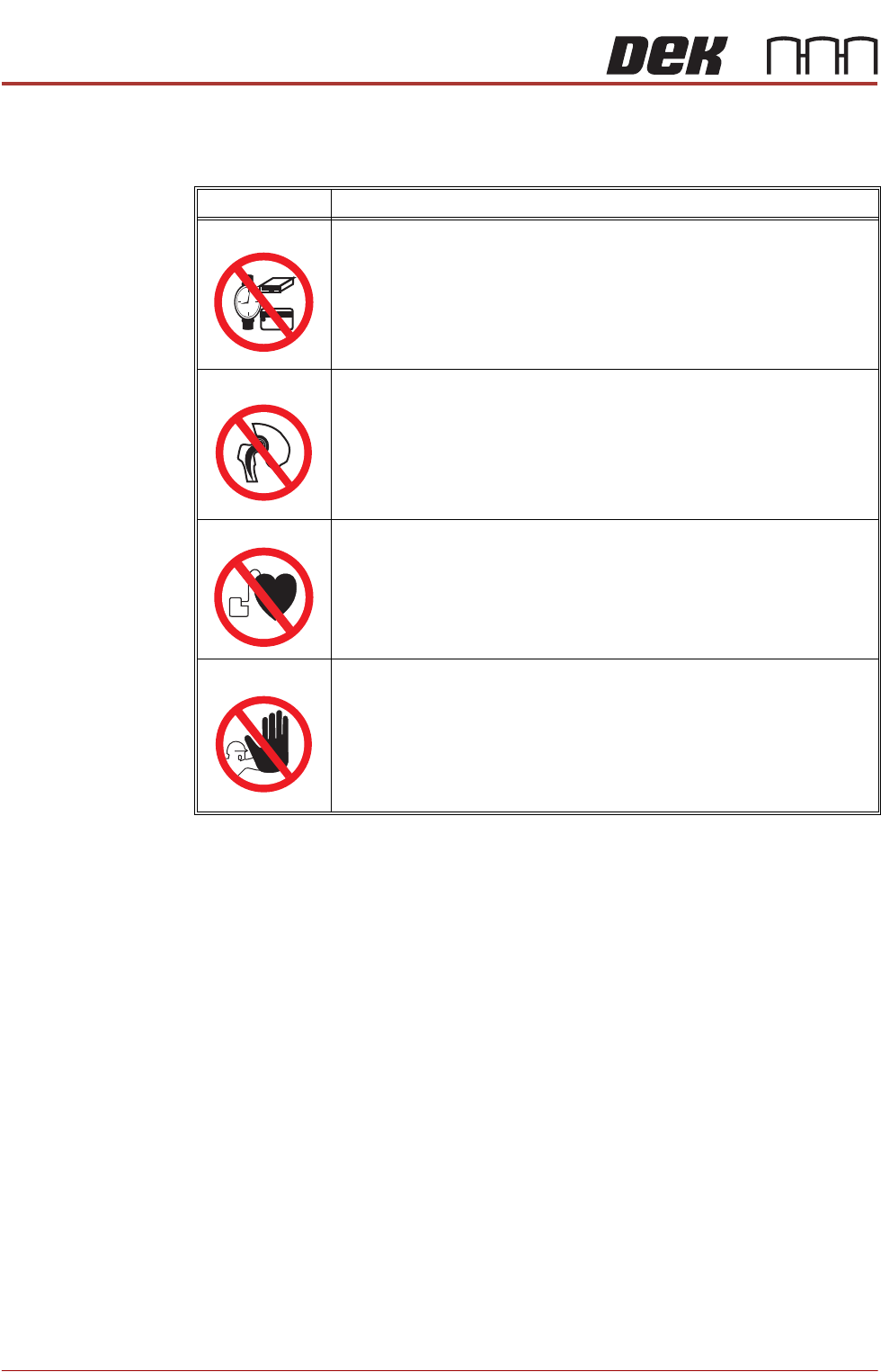
Prohibition Notices Prohibition notices draw the attention of users/maintainers to prohibiting behav-
iour likely to cause a risk to health or safety. The following table displays the
prohibition labels affixed to printer and displayed in the printer documentation:
SYMBOL DEFINITION
PROHIBITION
STRONG MAGNETIC FIELD. A STRONG MAGNETIC FIELD EXISTS IN
THE VICINITY OF THE LINEAR MOTORS THAT MAY ACT UPON FER-
ROUS OBJECTS WHOSE MOVEMENTS COULD LEAD TO PERSONAL
INJURY AND/OR DAMAGE TO THE MACHINE.
PROHIBITION
STRONG MAGNETIC FIELD. A STRONG MAGNETIC FIELD EXISTS IN
THE VICINITY OF THE LINEAR MOTORS THAT REPRESENT A SERI-
OUS HAZARD TO PEOPLE FITTED WITH METALLIC IMPLANTS.
PROHIBITION
ELECTROMAGNETIC FIELD. AN ELECTROMAGNETIC FIELD EXISTS
WITHIN THE MACHINE FROM THE LINEAR MOTORS. THESE MAY
PRESENT A HAZARD TO PEOPLE FITTED WITH AN IMPLANTED CAR-
DIAC DEVICE. THE MOTOR MANUFACTURER RECOMMENDS A SAFE
DISTANCE OF AT LEAST 400MM.
PROHIBITION
MACHINE COVERS. IN ORDER TO PROTECT PERSONNEL AND TO
PREVENT DAMAGE TO THE MACHINE, COVERS ARE FITTED TO THE
MACHINE FRAME. THESE PANELS MUST ONLY BE REMOVED BY
SUITABLY QUALIFIED PERSONNEL.