88192278-01-19 Installation Master.pdf - 第145页
PRINTER PREPARATION PRINTER ASSEMBLY Chapter Issue 15, May 20 Installation Manual 4.43 High Throughput Conveyors (HTC) The following procedure details how to install the HTC auxiliary conveyors to the printer . Th is ins…
PRINTER PREPARATION
PRINTER ASSEMBLY
4.42 Installation Manual Chapter Issue 15, May 20
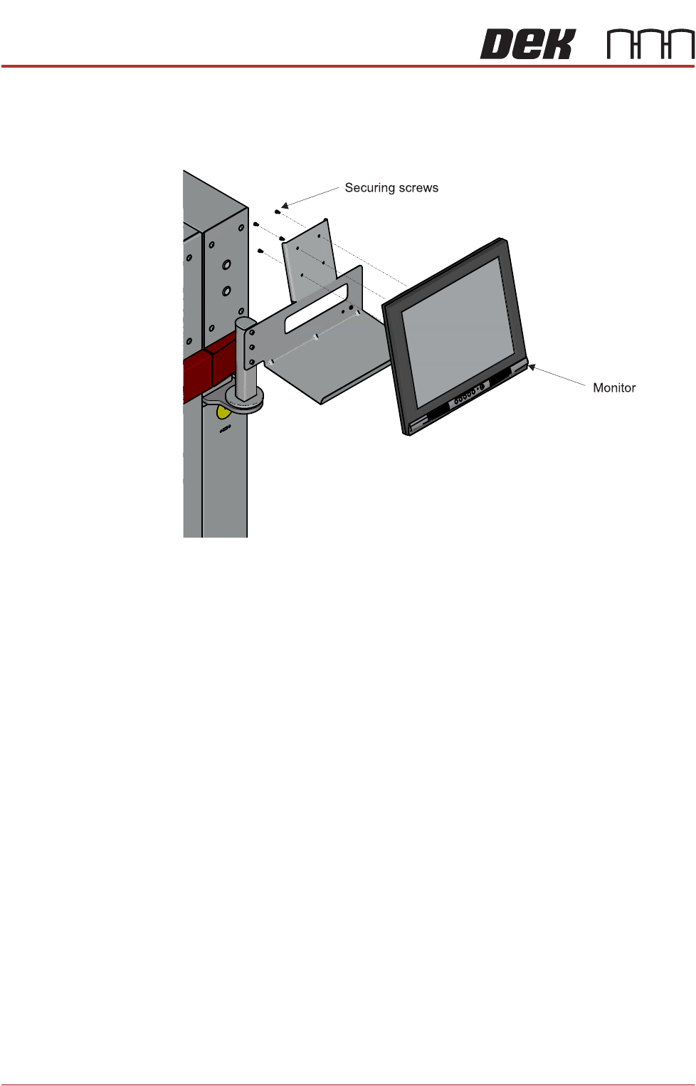
5. Fit and secure the monitor to the monitor bracket.
6. Connect the following cables to the monitor:
• Monitor Power Cable (DC)
•VGA Cable
7. Place the keyboard on the bracket and feed the keyboard cable into the
printer.
8. Refit the front cover.
PRINTER PREPARATION
PRINTER ASSEMBLY
Chapter Issue 15, May 20 Installation Manual 4.43
High Throughput
Conveyors (HTC)
The following procedure details how to install the HTC auxiliary conveyors to
the printer. This installation procedure is for a printer product transfer in the left
to right direction.
To install the auxiliary conveyors, remove the left and right safety covers and
the following panels (as detailed in the Covers chapter):
• Type 1 covers - front and rear corner panels and the centre side panel on
both sides
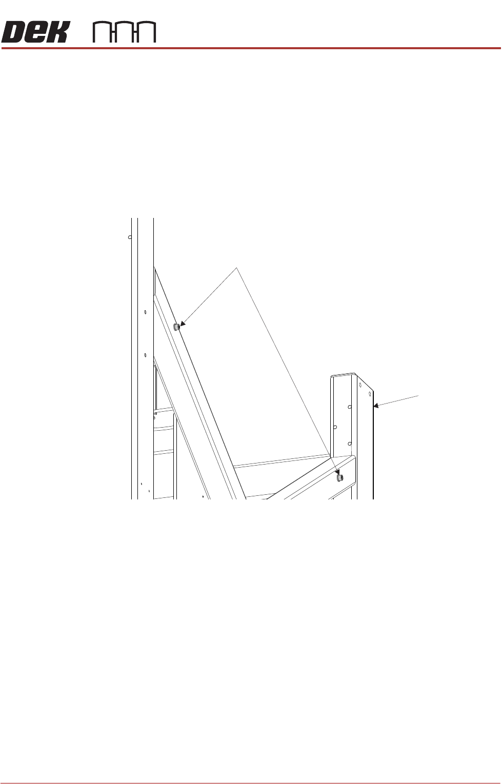
1. Remove the four auxiliary conveyor securing bolts from the holes in the
printer frame (two either side).
2. On the right hand side of the printer, align the holes in the right hand auxiliary
conveyor mounting bracket to the holes in the printer frame and refit the
Auxiliary Conveyor Securing Bolts
Machine Frame
PRINTER PREPARATION
PRINTER ASSEMBLY
4.44 Installation Manual Chapter Issue 15, May 20
auxiliary conveyor securing bolts.
NOTE
The right hand auxiliary rail has two pneumatic solenoids mounted on its
front rail, the left hand auxiliary rail only has one.
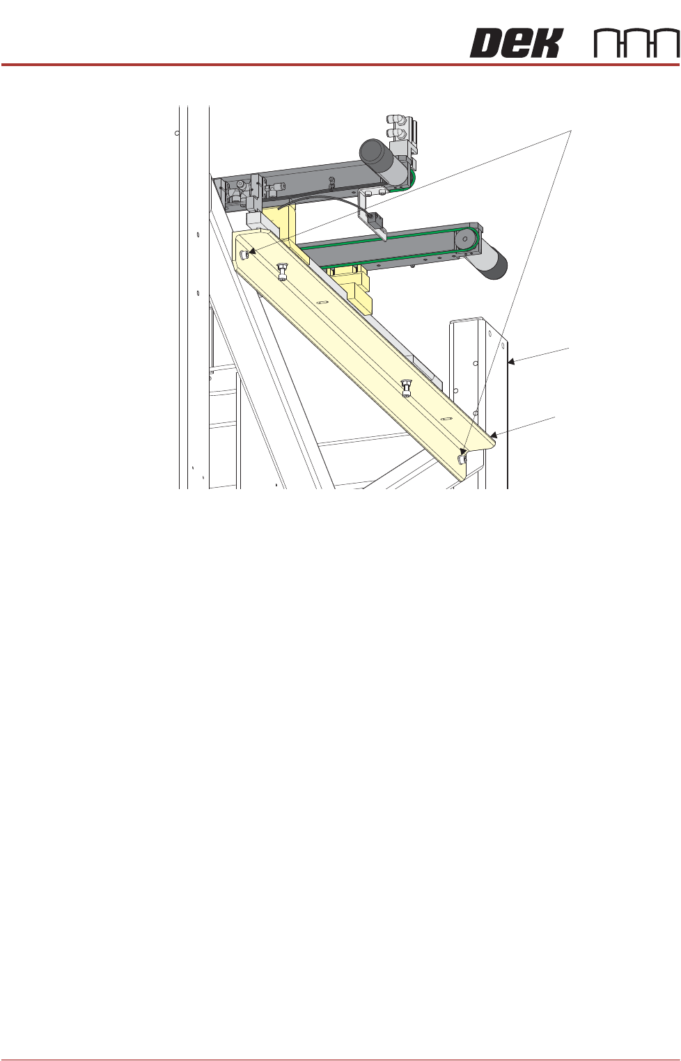
3. Align the auxiliary conveyor to the print station rails and tighten the securing
bolts.
4. On the left hand side of the printer, align the holes in the left hand auxiliary
conveyor mounting bracket to the holes in the printer frame and refit the
auxiliary conveyor securing bolts.
5. Align the auxiliary conveyor to the print station rails and tighten the securing
bolts.
6. Connect the following to the left hand auxiliary conveyor:
• M27PL07 to M27SK07 on the rear rail
• M27PL06 to M27SK06 on the front rail
• Clip M27SK05 into its bracket on the front rail and connect M27PL05 to
M27SK05
• Electrical connection to M27SOL02 (pneumatic solenoid) on the front rail
• Pneumatic feed to the input connector of M27SOL02
7. Connect the following to the right hand auxiliary conveyor:
• M27PL17 to M27SK17 on the rear rail
• M27PL16 to M27SK16 on the front rail
• Clip M27SK14 into its bracket on the front rail and connect M27PL14 to
M27SK14
• Electrical connection to M27SOL01 (pneumatic solenoid) on the front rail
Auxiliary Conveyor Securing Bolts
Auxiliary Conveyor
Mounting Bracket
Machine Frame