88192278-01-19 Installation Master.pdf - 第148页
PRINTER PREPARATION PRINTER ASSEMBLY 4.46 Installation Manual Chapter Issue 15, May 20 Auxiliary Conveyor to Print Station Gap T o check and if required adjust the gaps between the print station rail and the auxiliary co…
PRINTER PREPARATION
PRINTER ASSEMBLY
Chapter Issue 15, May 20 Installation Manual 4.45
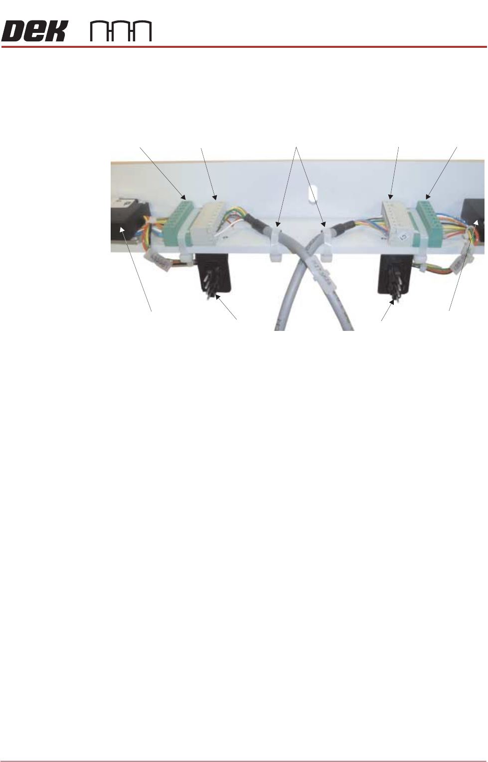
• Electrical connection to M27SOL03 (pneumatic solenoid) on the front rail
• Pneumatic feed to the input connector of M27SOL03
• M27SK24 to M27PL24 and M27SK25 to M27PL25 of the belt speed motor
controllers. Fit two cable ties to secure the cables to the mounting bracket
• 8SK21 to 8PL21 and 8SK23 to 8PL23 of the belt speed motor controllers
8. Cable tie any loose cables together to prevent them catching or rubbing on
any moving parts.
M27PL24 M27SK24 M27SK25 M27PL25
8PL21 8PL23
Front Belt Speed
Motor Controller
Rear Belt Speed
Motor Controller
Cable Ties
View on Underside of Right Hand Auxiliary Conveyor Mounting Bracket
PRINTER PREPARATION
PRINTER ASSEMBLY
4.46 Installation Manual Chapter Issue 15, May 20
Auxiliary Conveyor
to Print Station
Gap
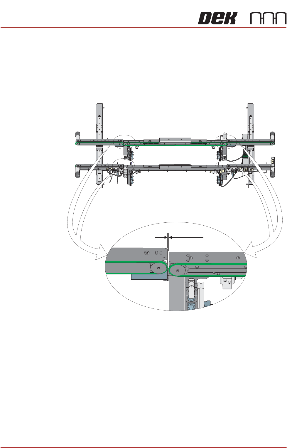
To check and if required adjust the gaps between the print station rail and the
auxiliary conveyors carry out the following procedure:
NOTE
To carry out this procedure on the front rail, the board stops between the print
station and the auxiliary conveyors must be removed.
1. Using feeler gauges, ensure that the gap between the print station and the
auxiliary conveyors (in four positions) is 3.5mm ±0.5mm.
2. If adjustment is required, loosen the locking nuts on the two auxiliary
Front View of HTC Rails
3.5 ±0.5mm
PRINTER PREPARATION
PRINTER ASSEMBLY
Chapter Issue 15, May 20 Installation Manual 4.47
conveyor height adjustment bolts.
3. Adjust the position of the conveyor to obtain the 3.5mm ±0.5mm gap
between the front and rear rails of the auxiliary conveyor and the front and
rear rails of the print station.
4. Re-tighten the locking nuts disturbed in Step 2 and re-check the gap
measurement.
5. On completion, carry out Auxiliary Conveyor Front Rail Parallelism check.
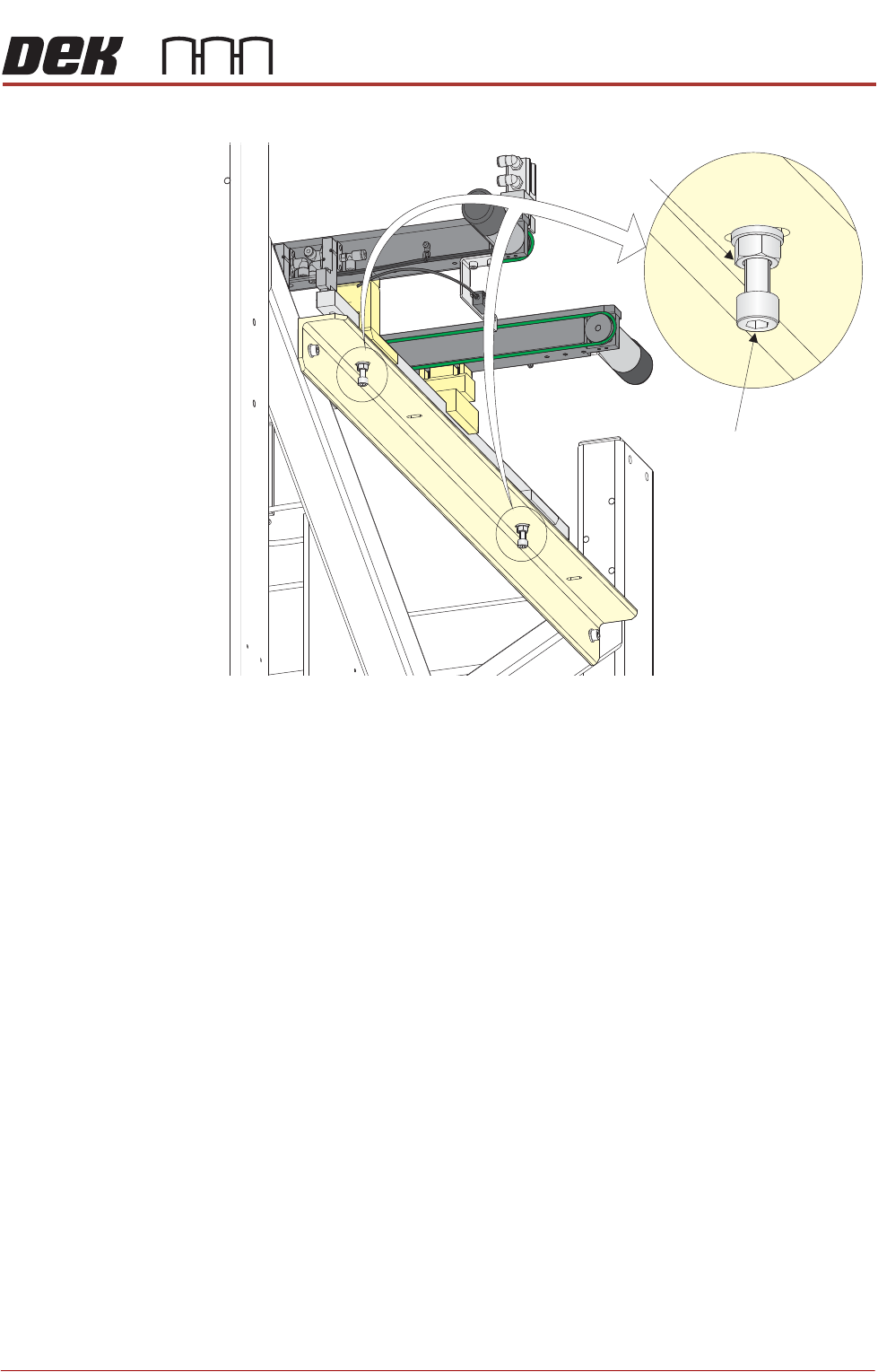
Auxiliary Conveyor
Levelling
To check and if required adjust the levelling of the auxiliary conveyors, carry out
the following procedure:
1. Manually adjust the auxiliary conveyor rail width to 250mm.
2. Place a Board Clamp Setting Plate Part No. 140403 onto the auxiliary
conveyor transport belts.
3. Place a spirit level on top of the setting plate and check the levelness of the
Auxiliary Conveyor
Height Adjustment
Bolt
Locking Nut