88192278-01-19 Installation Master.pdf - 第152页
PRINTER PREPARATION PRINTER ASSEMBLY 4.50 Installation Manual Chapter Issue 15, May 20 the mechanism from the print carriage. Removing Drip T ray 1. Close the speed control valves on the drip tra y actuator . 2. Remove t…
PRINTER PREPARATION
PRINTER ASSEMBLY
Chapter Issue 15, May 20 Installation Manual 4.49
NOTE
Auxiliary conveyor height settings and parallelism is checked after Printer
Power Up Sequence.
ProFlow & ProFlow
ATx
The printer is shipped with the squeegee mechanism fitted as standard. To
change the printer to ProFlow or ProFlow ATx, use the following procedures:
• Remove Squeegee Pressure Mechanism
• Remove Drip Tray
Remove Squeegee
Pressure
Mechanism
To remove the squeegee pressure mechanism, carry out the following
procedure:
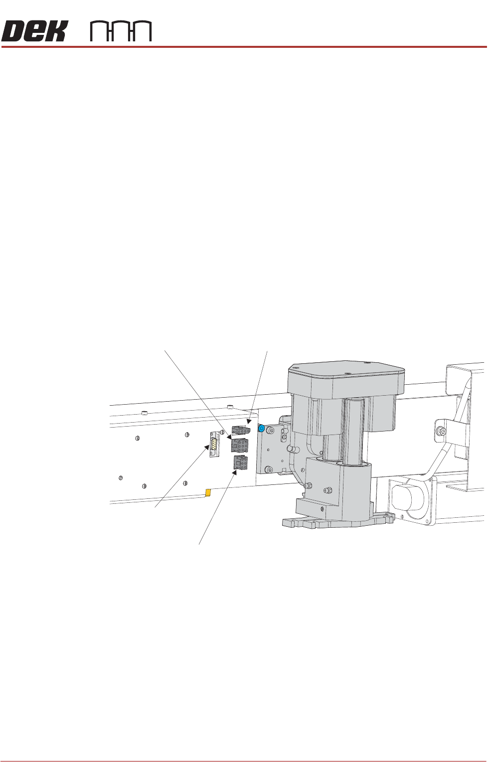
1. Disconnect the four squeegee mechanism connectors from the print
carriage, left hand side:
• Rear Squeegee Motor
• Front Squeegee Motor
• Home Sensors
• Squeegee Pressure Amplifier
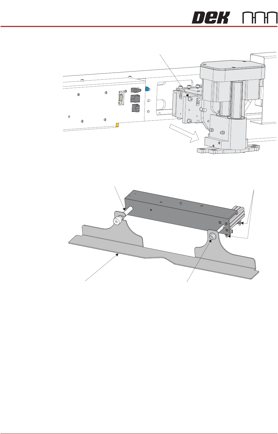
2. Loosen the four captive screws securing the squeegee printhead
mechanism to the print carriage using a 4mm Allen key. Carefully remove
Rear Squeegee
Motor (9SK17)
Front Squeegee
Motor (9SK16)
Home Sensors
(9SK08)
Squeegee Pressure
Amplifier (N3SK16)
PRINTER PREPARATION
PRINTER ASSEMBLY
4.50 Installation Manual Chapter Issue 15, May 20
the mechanism from the print carriage.
Removing Drip Tray 1. Close the speed control valves on the drip tray actuator.
2. Remove the securing screw attaching the drip tray to the actuator piston.
3. Slide the drip tray off the bearing on the drip tray guide shaft.
4. Remove the drip tray guide shaft if fitting ProFlow ATx.
Captive Screw (in 4 positions)
Drip Tray
Drip Tray Guide Shaft
Securing Screw
Speed Control Valves
PRINTER PREPARATION
PRINTER ASSEMBLY
Chapter Issue 15, May 20 Installation Manual 4.51
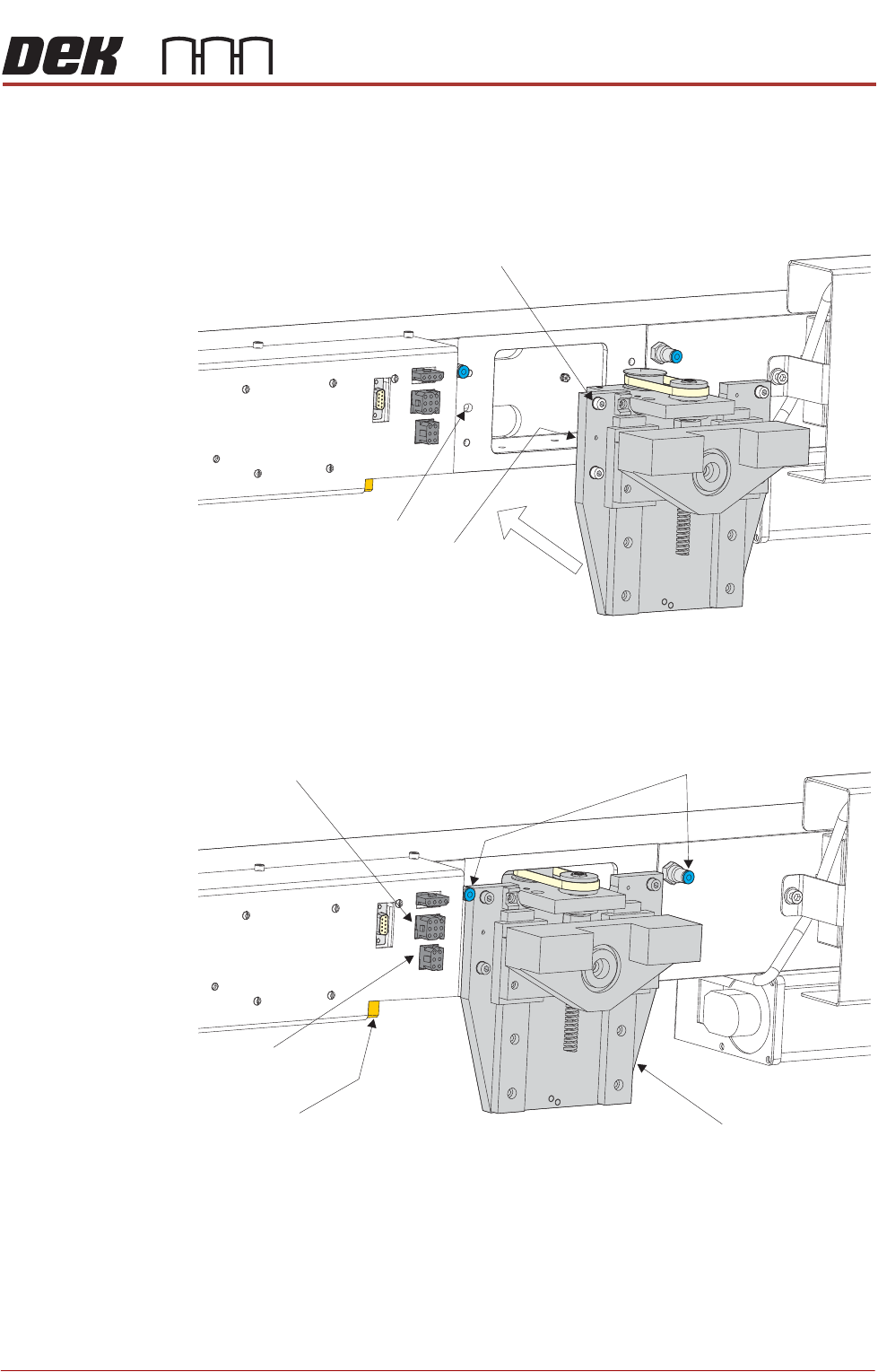
Fitting ProFlow To fit ProFlow to the printer, carry out the following procedure:
1. Carefully position the ProFlow printhead mechanism so that both locating
dowels locate into the print carriage locating holes. Secure the unit to the
print carriage by means of the four captive screws.
2. Connect the following connectors to the print carriage, left hand side:
• ProFlow motor connector 9PL17 into 9 way socket 9SK17
• ProFlow home sensor connector 9PL08 into 6 way socket 9SK08
3. Fit the pressure mechanism part of the ProFlow unit to the ProFlow
printhead mechanism bearing block by means of the two securing bolts.
Captive Screw (in 4 positions)
Locating Dowel
(in 2 positions)
Print Carriage Locating
Hole (in 2 positions)
Pneumatic Connectors
ProFlow Motor
(9SK17)
Home Sensor
(9SK08)
ProFlow Paste Level
Sensor (9PL61)
ProFlow Printhead
Mechanism