88192278-01-19 Installation Master.pdf - 第154页
PRINTER PREPARATION PRINTER ASSEMBLY 4.52 Installation Manual Chapter Issue 15, May 20 T ighten using a 5mm Allen key . 4. Ensure that the locking clip on the pressure mechanism is pressed over to the right and clicks in…
PRINTER PREPARATION
PRINTER ASSEMBLY
Chapter Issue 15, May 20 Installation Manual 4.51
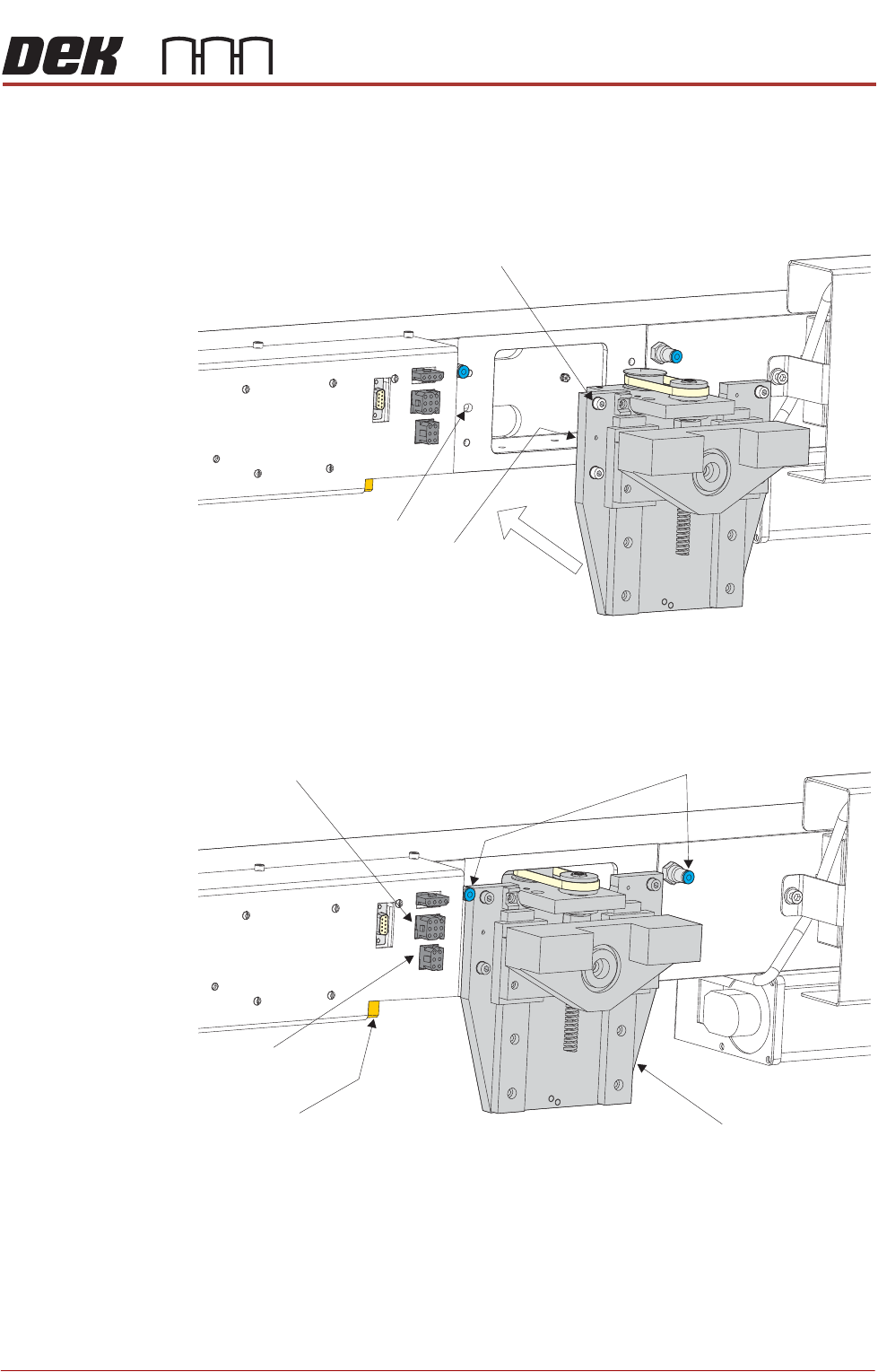
Fitting ProFlow To fit ProFlow to the printer, carry out the following procedure:
1. Carefully position the ProFlow printhead mechanism so that both locating
dowels locate into the print carriage locating holes. Secure the unit to the
print carriage by means of the four captive screws.
2. Connect the following connectors to the print carriage, left hand side:
• ProFlow motor connector 9PL17 into 9 way socket 9SK17
• ProFlow home sensor connector 9PL08 into 6 way socket 9SK08
3. Fit the pressure mechanism part of the ProFlow unit to the ProFlow
printhead mechanism bearing block by means of the two securing bolts.
Captive Screw (in 4 positions)
Locating Dowel
(in 2 positions)
Print Carriage Locating
Hole (in 2 positions)
Pneumatic Connectors
ProFlow Motor
(9SK17)
Home Sensor
(9SK08)
ProFlow Paste Level
Sensor (9PL61)
ProFlow Printhead
Mechanism
PRINTER PREPARATION
PRINTER ASSEMBLY
4.52 Installation Manual Chapter Issue 15, May 20
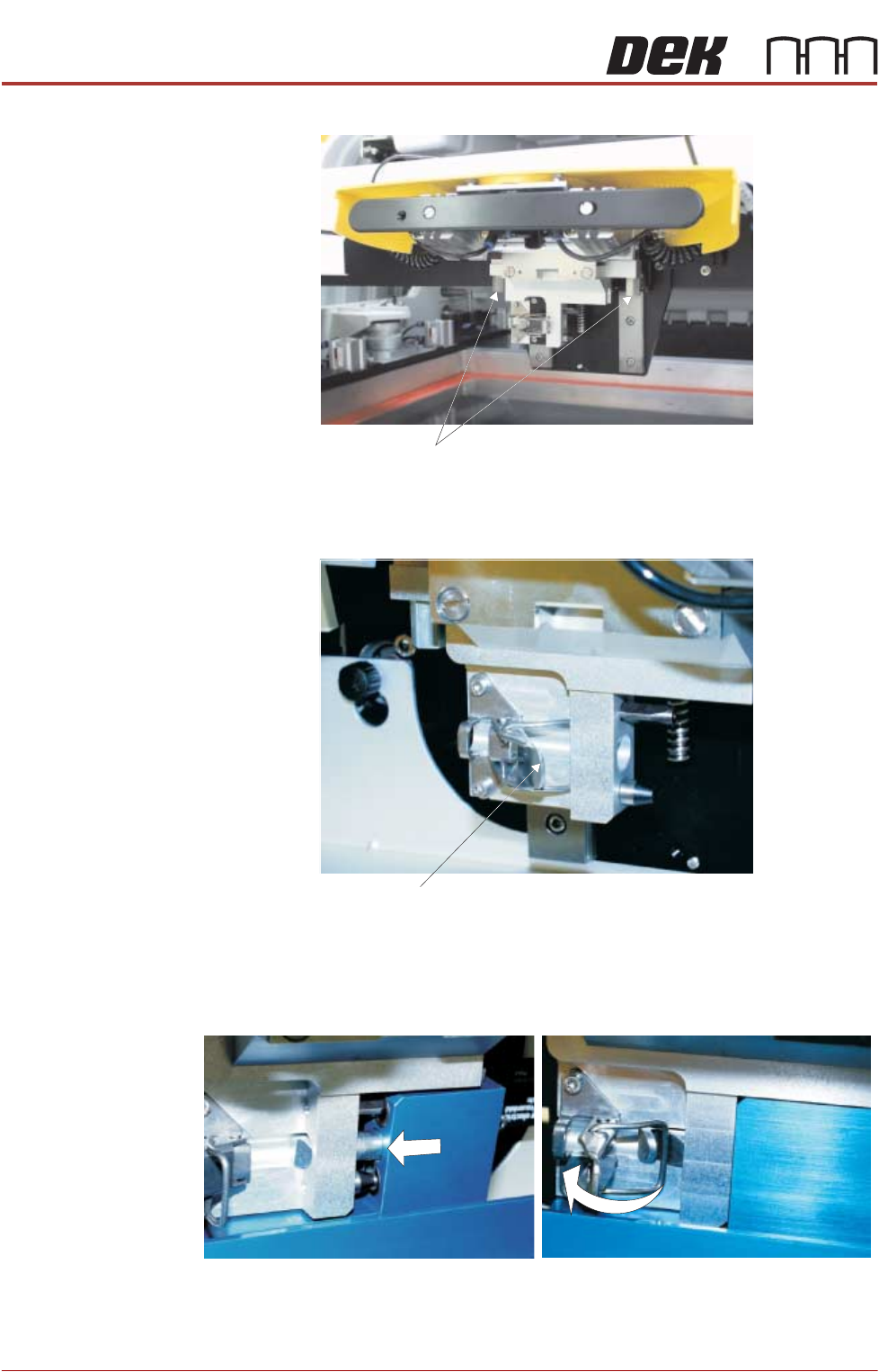
Tighten using a 5mm Allen key.
4. Ensure that the locking clip on the pressure mechanism is pressed over to
the right and clicks into place, as shown in the figure below. This ensures
that the locking clip is in the correct position to secure the transfer head.
5. Locate and fit the ProFlow transfer head unit to the pressure mechanism by
means of the two locating dowels. Slide the unit onto the pressure
mechanism. Once the unit is slid fully home, it is secured by closing the
locking clip.
6. Connect both curly air lines to the self-seal pneumatic connectors situated
either side of the ProFlow printhead mechanism, figure in Step 7 refers.
7. Fit the electrical connection 9SK61 ProFlow Paste Level Sensor from the
Securing Bolts
Locking Clip
PRINTER PREPARATION
PRINTER ASSEMBLY
Chapter Issue 15, May 20 Installation Manual 4.53
ProFlow unit into the connector (9PL61) located on the left hand side of the
ProFlow, on the print carriage, figure in Step 7 refers.
NOTE
a. 1) An amplifier is connected to 9PL61 and the connection is made to
9PL62 on the amplifier.
b. 2) This electrical connection informs the printer of ProFlow fitment and
must always be connected whilst the ProFlow unit is fitted otherwise
damage may occur if printer is run.
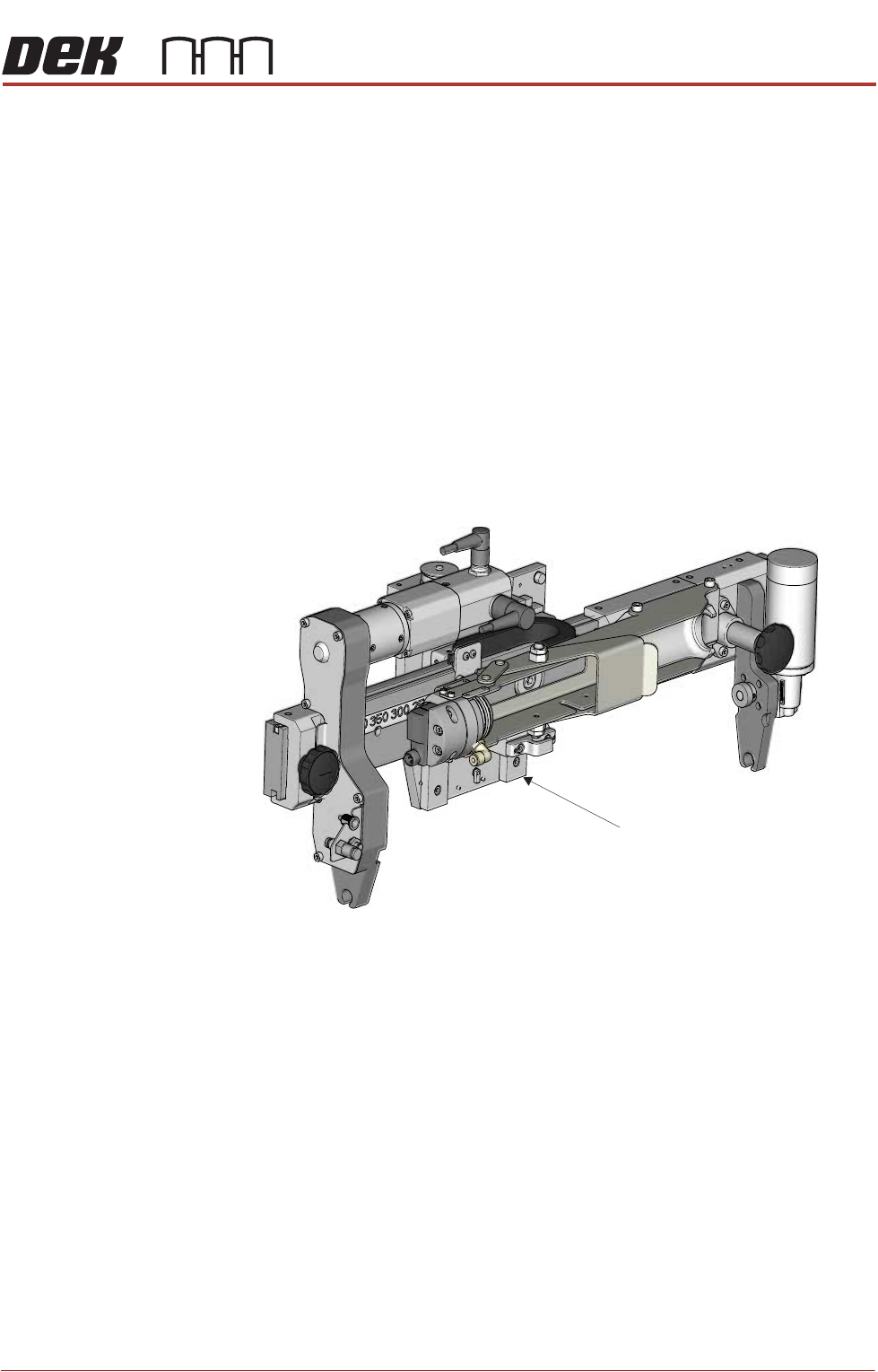
Fitting ProFlow
ATx
To fit ProFlow ATx to the printer, carry out the following procedures:
• Fit ProFlow ATx System Mount
• Fit Transfer Head
• Level Transfer Head
• Fit Print Medium Cartridge
Mount Plate