88192278-01-19 Installation Master.pdf - 第164页
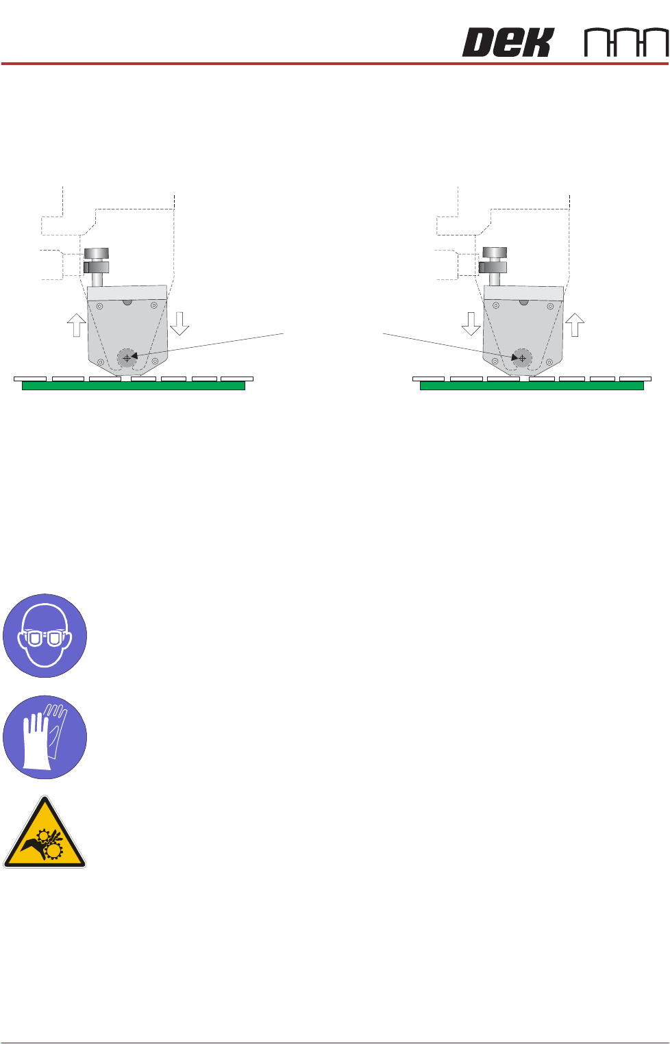
PRINTER PREPARATION PRINTER ASSEMBLY 4.62 Installation Manual Chapter Issue 15, May 20 T urning the levelling screws clockwise lowers the front of the transfer head. T urning the levelling screws coun ter-clockwise raise…
PRINTER PREPARATION
PRINTER ASSEMBLY
Chapter Issue 15, May 20 Installation Manual 4.61
• Pistons Up Air Feed
15. Turn the two locking clips, on the base cover, to the unlock position (pointing
upwards).
16. Remove the sealing plug from the transfer head.
17. Remove the base cover from the transfer head.
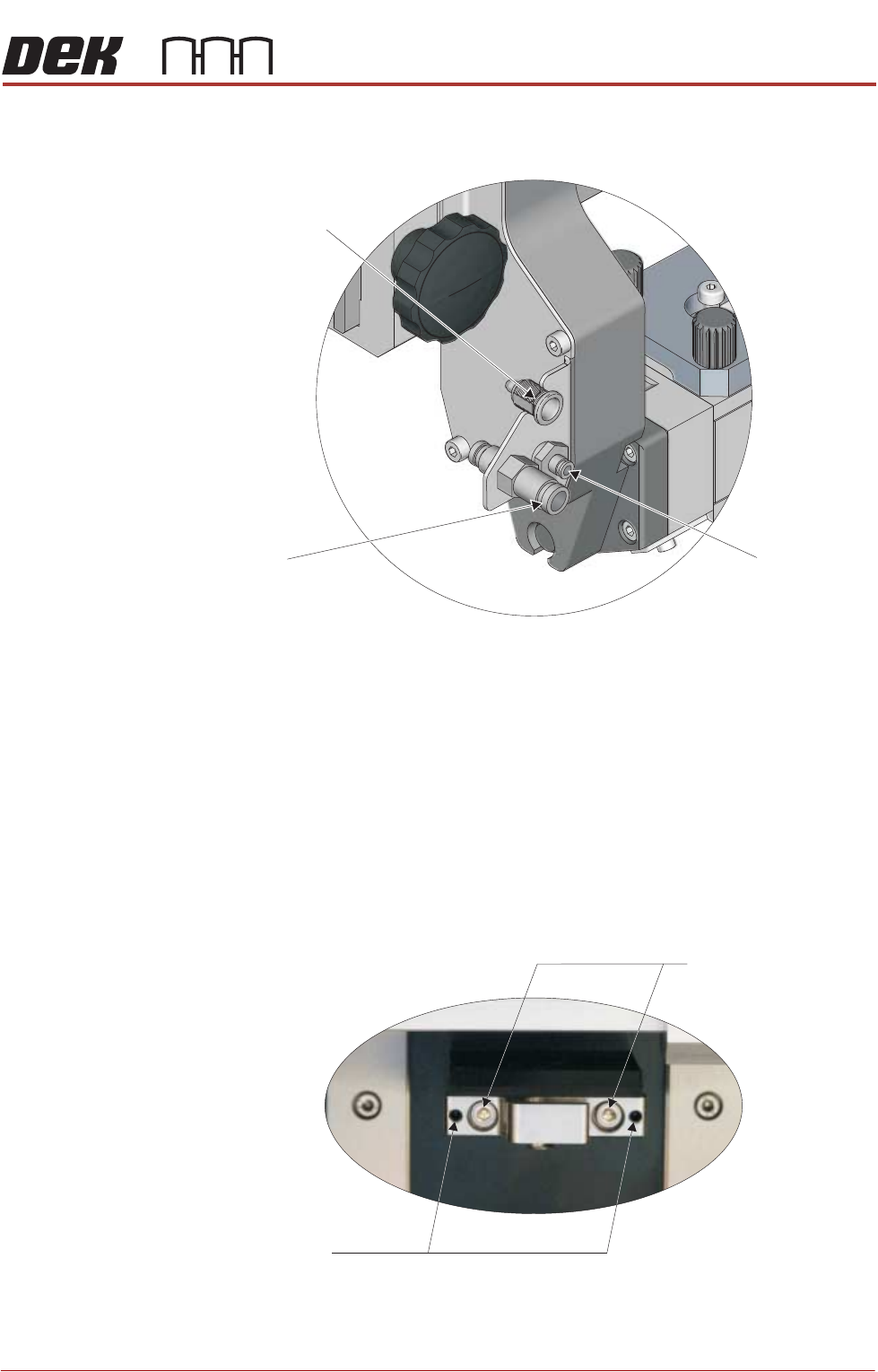
Levelling the
Transfer Head
For an even application of print medium, during both the forward and rearward
print-strokes, obtain equal pressure on the tips of the wiper blades by levelling
the transfer head against the stencil when under system pressure. To adjust the
level of the transfer head, carry out the following on the ProFlow ATx mount:
1. Loosen the two transfer head pin mount lock screws, using a 3mm Allen key.
2. Evenly adjust the two transfer head levelling screws, using a 2mm Allen key.
Print Medium Demand
Sensor 9SK106
Pistons Down
Air Feed
Pistons Up
Air Feed
View on Left Side of the ProFlow Mount
Transfer Head Vertical Pin Mount on ProFlow ATx Mount
Transfer Head
Levelling Screws
Pin Mount Lock Screws
PRINTER PREPARATION
PRINTER ASSEMBLY
4.62 Installation Manual Chapter Issue 15, May 20
Turning the levelling screws clockwise lowers the front of the transfer head.
Turning the levelling screws counter-clockwise raises the front of the trans-
fer head.
3. Tighten the two transfer head pin mount lock screws, using a 3mm Allen key.
4. Perform a print operation.
5. Inspect the print medium application; if further levelling is required, repeat
the procedure.
Fit Print Medium Cartridge
MANDATORY
TOXIC CHEMICALS MAY BE PRESENT. EYE PROTECTION MUST BE WORN.
MANDATORY
TOXIC CHEMICALS MAY BE PRESENT. SAFETY GLOVES MUST BE WORN.
WARNING
MOVING PARTS. MOVING PARTS ARE PRESENT IN THE VICINITY OF THIS
WARNING LABEL, THESE PARTS HAVE THE POTENTIAL TO CAUSE INJURY.
NOTE
The following procedure assumes that an empty cartridge is fitted; if this is not
the case, open the lever arm (Step 4) and begin the procedure at Step 9 - “Fit
the new print medium cartridge to the filler tube assembly”.
View on Transfer Head Left Hand End (Through ProFlow Mount)
Transfer Head’s
Point of Rotation
Levelling Screws Clockwise
Levelling Screws Counter-clockwise
PRINTER PREPARATION
PRINTER ASSEMBLY
Chapter Issue 15, May 20 Installation Manual 4.63
To fit a new print medium cartridge to the ProFlow ATx system, carry out the
following:
1. Open the printer cover.
2. Pull the lever arm towards the left side of the printer.
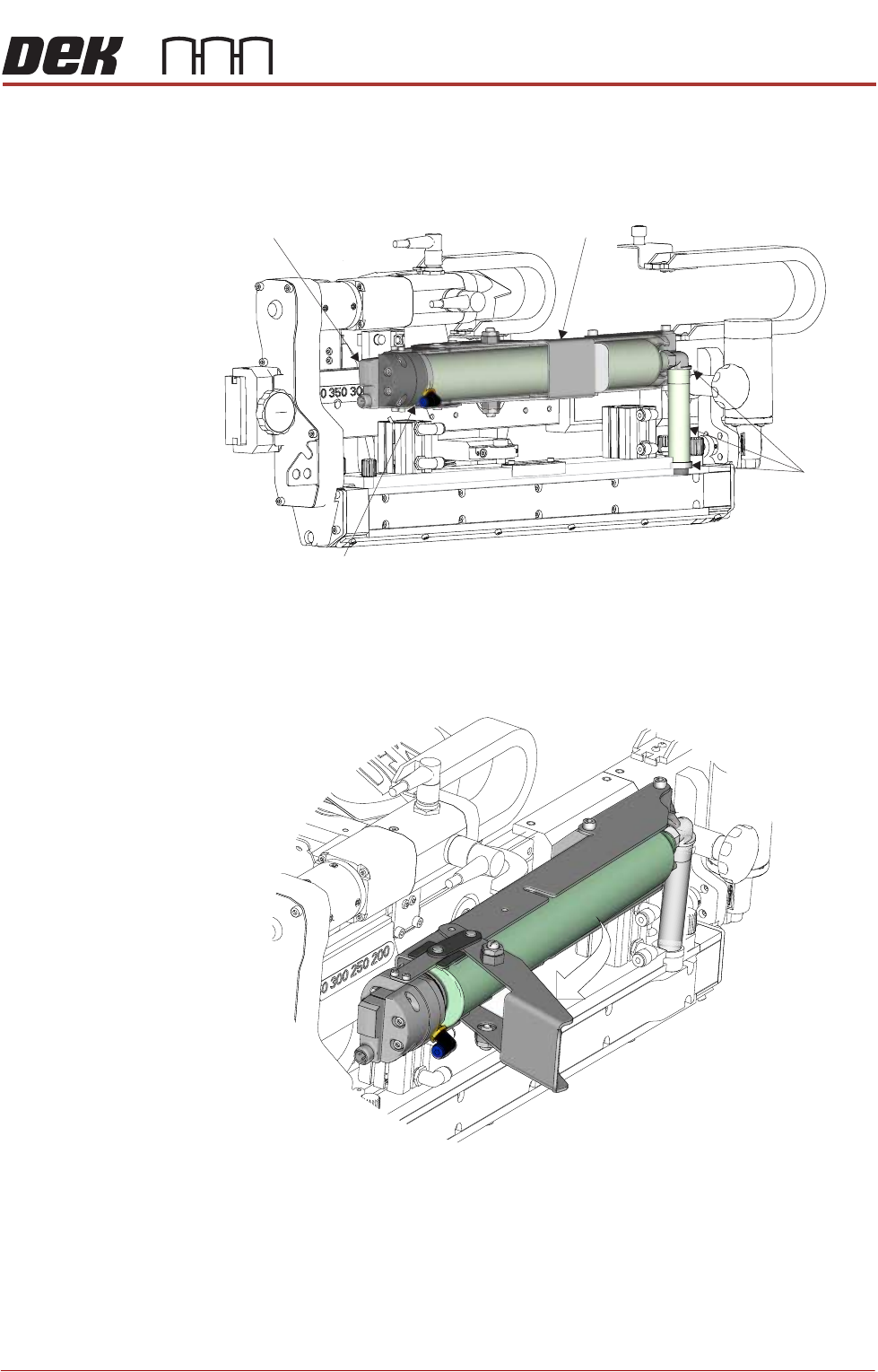
View on Front
Print Medium
Level Sensor
Print Medium
Cartridge Holder
Print Medium
Filler Tube
Assembly
Print Medium Pneumatic
Delivery Mechanism
View on Left Front of ProFlow ATx System